
A Bidirectional Level-Shifting Buffer for Raspberry Pi
In scenarios where both input and output need to interface with 5V logic, a bidirectional level shifter is necessary. When speed is not a critical factor and the load current is low, a simple resistor divider may suffice. However, for high-speed applications, a dedicated level shifter is required. The Analog Devices ADG3300 is designed for such applications. One of the key advantages of using the ADG3300 is its internal one-shot generator, which ensures fast rising and falling edges of signal transients, enabling operation at speeds well into the MHz range. Another benefit of the ADG3300 is the absence of a directional control pin, allowing simultaneous bidirectional level shifting. However, the ADG3300 is not intended for driving high current loads; it is designed primarily for logical gate applications, delivering current well below a few mA.
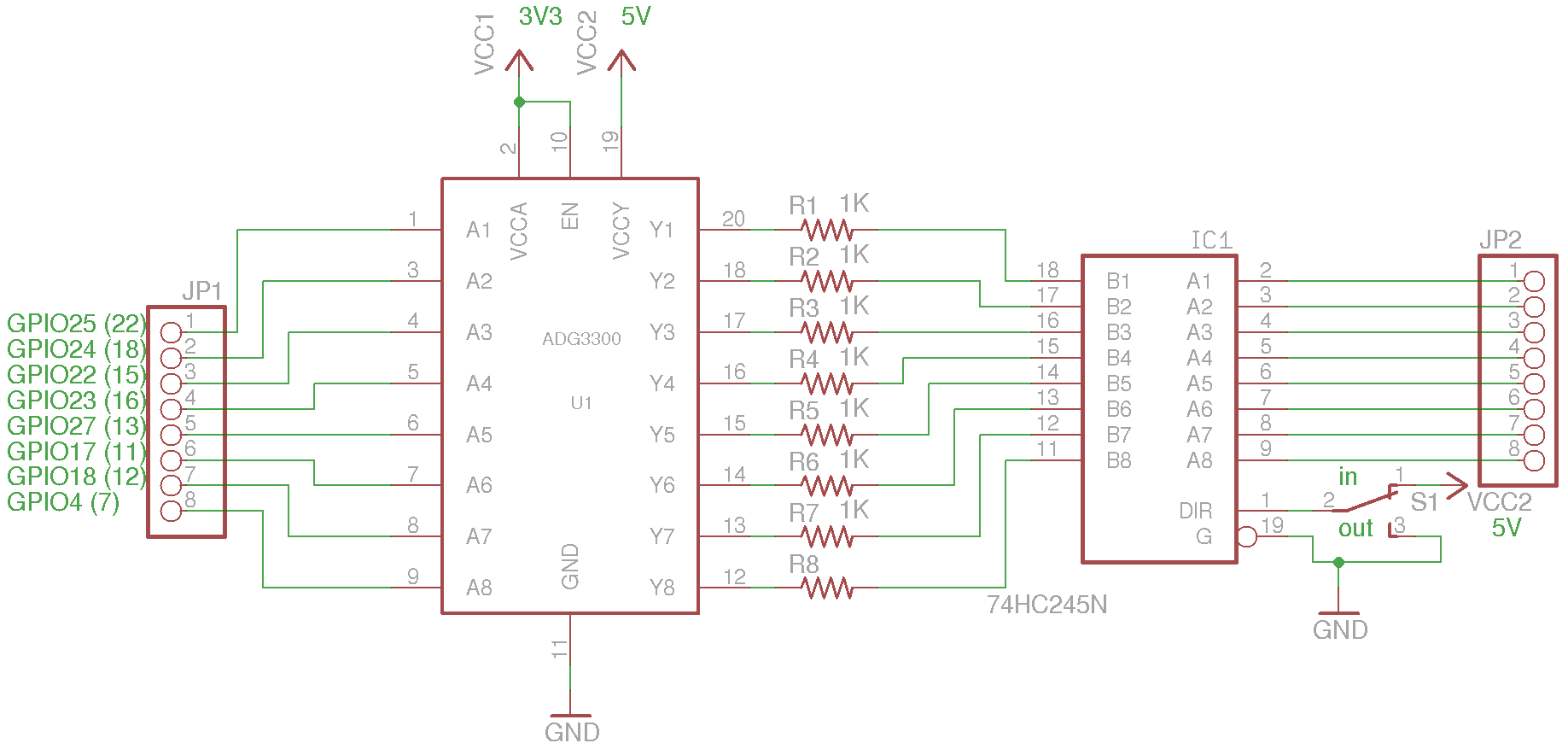
To enhance the output current capability, the ADG3300 can be interfaced with a bus transceiver such as the 74HC245. The following schematic illustrates a bidirectional level-shifting buffer utilizing both the ADG3300 and 74HC245: the 74HC245's Vcc (not shown) is connected to Vcc2, and the input/output direction is controlled by a direction pin. In this example, the direction pin is managed by a switch, but it could also be controlled by a microcontroller’s output. 1K resistors are included to prevent parasitic oscillation. For ease of experimentation, the ADG3300 and 74HC245 are placed on separate boards and connected via a ribbon cable. A jumper is also included to switch Vcc2 between 3.3V and 5V, facilitating the use of the same setup for both voltage levels. Alternatively, a bus transceiver chip such as the SN74LVC4245A can be used for both level shifting and buffering, but the circuit described above is arguably more versatile for experimentation purposes.
This setup provides a robust solution for interfacing the Raspberry Pi with higher voltage logic levels while ensuring signal integrity and current capability, making it suitable for various applications in electronic design.The current sourcing/sinking capability of the I/O pins on Raspberry Pi is quite limited. According to the Wiki page, the current limit for each I/O block (e. g. GPIO0 through GPIO27 combined) comes at only 26 mA maximum, which is only capable of driving a couple of LEDs at a time. Also the I/O pins are 3. 3V only, and going beyond the current or v oltage limit could result in permanently damages to the chip. If we only need to boost the output current, we could use a simple transistor or MOSFET to overcome the current limit. Alternatively, we could use a Darlington array chip such as ULN2003 for the task. ULN2003 ²s on-state input voltage is well below 3. 3V and can be driven directly from Raspberry Pi`s I/O pins conveniently. Keep in mind though, due to the limited current capability of Raspberry Pi the maximum speed at which ULN2003 can be driven is limited due to its relatively large input capacitance and input current requirement.
So while ULN2003 can deliver a rather high load current, it is only suitable for interfacing with slower peripherals that operate at a speed no higher than a couple hundred KHz. What if we need to interface both the input and output with 5V logic In this case, a bidirectional level-shifter is needed.
When speed is not an issue and the load current is low, a simple resistor divider may be used. For high speed applications however, we would need a dedicated level-shifter. Analog Devices` ADG3300 is designed for this very situation. One of the key benefits of using ADG3300 is that this chip has an internal one-shot generator that ensures fast rising and falling edge of the signal transients and thus can be driven at a speed well into the MHz range. Another benefit of AD3300 is that no directional control pin is needed, the level-shifting happens simultaneously both ways.
But ADG3300 cannot be used to drive high current load. In fact it is designed to drive logical gates only, which means that the current delivered is well under a few mA at the best. To improve the output current capability, we can interface the ADG3300 with a bus transceiver such as 74HC245.
The following schematic shows a bidirectional level-shifting buffer using both ADG3300 and 74HC245: 74HC245 ²s Vcc (not shown) is tied to Vcc2, and the input/output direction is controlled by the direction pin. In my example, the direction pin is controlled by a switch but it could be controlled via a microcontroller`s output as well.
The 1K resistors are added to prevent parasitic oscillation. To make it easier for experimentation, I put ADG3300 and 74HC245 on two separate boards and connected them via a ribbon cable. I also included a jumper to switch Vcc2 between 3. 3V and 5V so that I could use the same setup for both 3. 3V and 5V circuits. Of course, you could just use a bus transceiver chip such as SN74LVC4245A for both level-shifting and buffering.
But for an experimentation platform, the circuit shown above is arguably more versatile. 🔗 External reference
Related Circuits
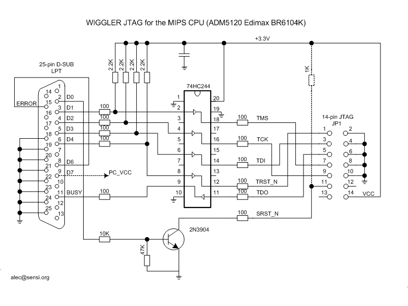
This type of cable is more complex than the unbuffered variant, yet it is still relatively easy to construct. The most commonly used cable in this category is the Wiggler cable, which is commercially available from Macraigor Systems. Priced...
The wah pedal operates before the amplifier but produces a low volume and a scratchy sound when the pedal is rocked back and forth. It functions correctly without the buffer. When placed in front of a Fuzz Face, no...
Most individuals seeking to modify and enhance their Spectrum often focus on the keyboard as a primary area for improvement. However, a straightforward replacement requires opening the computer, which can be discouraging for two main reasons. Firstly, this action...
This is a INA159 Dual-Polarity, Bidirectional Current-Shunt-Monitor Circuit. This circuit uses OPA340 because it has near rail-to-rail input and output swing. The INA159 is an integrated circuit designed for high precision current sensing applications. It is capable of measuring bidirectional...
When designed with general-purpose small-signal transistors, the bandwidth ranges from 50 MHz to 250 MHz, necessitating careful grounding and power supply decoupling. The simulation schematic illustrates a two-transistor buffer. Due to copyright issues, models from other sources are not...
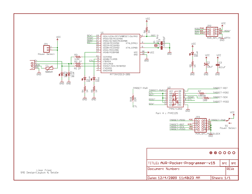
At the bottom, there is a 74AC125, which is a quad buffer with tri-state outputs. Numerous buffers of this type have been observed in programmers. The function of these buffers is not entirely clear, but it is assumed that...