
Spectrum Keyboard Buffer
The keyboard buffer circuit is designed to facilitate the integration of an external keyboard with the ZX Spectrum while ensuring compatibility with the existing system architecture. The circuit employs a 74LS27 NOR gate to monitor the IORQ, RD, and A0 lines, which are essential for determining the operational state of the keyboard port. When the conditions are met (all inputs LOW), the NOR gate's output transitions to HIGH, signaling the Z-80A microprocessor to read data from the external keyboard buffer instead of the internal keyboard.
To implement this solution, the keyboard buffer circuit must be connected to the ZX Spectrum's expansion port, ensuring that it does not interfere with the existing circuitry. The design includes appropriate pull-up resistors on the data lines to maintain the required HIGH state when no keys are pressed. Furthermore, the circuit should be housed in a protective enclosure to prevent physical damage during installation and operation.
In summary, the keyboard buffer represents a practical modification for ZX Spectrum users, allowing for enhanced keyboard functionality without compromising the integrity of the original hardware. The careful design and implementation of the buffer ensure that users can upgrade their systems while maintaining warranty coverage and minimizing the risk of damage.Most people who want to modify and improve their Spectrum look first at the keyboard as a prime area for change. But straightforward replacement involves digging around inside the computer - something of a put-off, for two important reasons.
To begin with it might nullify the guarantee from Sinclair and, frankly, there`s just no-one else around to undertake this kind of repair work (there`s no published circuit diagram and a lack of certain specialised parts). Secondly, it`s easy for damage to occur when fitting the keyboard to the computer or mounting the keyboard in a separate case (which requires the removal of the complete circuit board from the casing of the computer). So what`s outlined here is a keyboard buffer that fits on the back of the ZX Spectrum, connecting to the real expansion port.
It can easily be fitted or unplugged for testing, and should your Spectrum develop a fault, it can be removed without trace for guarantee purposes. The Sinclair keyboard, like many others, works on a matrix of keys where each key connects up two wires.
The combination of the incoming and outgoing wires is continually being tested by the computer to see which one has been pressed. On the ZX Spectrum the keyboard has eight incoming wires - the upper eight address lines. These are tested by holding only one of them to a Binary 0 (a LOW signal) and seeing what the result is on the incoming (data) lines.
If a switch has been pressed on the address line being tested, then the LOW signal will be passed on to the data line to which it is connected. Until then the data line will be held to a Binary 1 by the resistors connected to the five data lines.
In the keyboard layout diagram (Figure 1) the keys as you can see are arranged in a similar order to the keyboard (but not in the familiar QWERTY layout). The five data line connections are shown at the top and the address lines at the sides. There is only one address line and one data line combination that can be produced by each key. The `A` key, for instance, will operate only when the A9 address line is tested The `scanning` of the keyboard (as it is called) is done by use of an IN A(C) instruction in machine code which lowers the address lines in turn, starting with A8 and progressing to A15, checking for a keypress on the data lines as it does so.
It uses the B and C registers inside the Z-80A to give the 16-bit address (which is put out on the address lines A0 to A15). This is done every 1/50th of a second using the timer within the ULA to trigger an INTERRUPT instruction to the Z-80A microprocessor.
The keyboard port is referred to as FE in hexadecimal notation or 254 in decimal, but operates as long as the A0 address line is a LOW signal (Binary 1). The electronics for the port is located within the ULA, and the data lines must be connected through the ULA to the microprocessor only when the correct address is detected.
Connecting them straight to the data lines of the Z-80A would cause utter confusion as both the address and data lines are used for other devices as well, like the RAM. The keyboard buffer`s port must operate in the same way as that of the ZX Spectrum in order to work properly - but with modifications such that the keyboard connected to the buffer will override the internal keyboard.
The ULA only uses three lines to tell it when the keyboard port should operate and we shall do the same. The IORQ line determines that it is an IN or an OUT instruction, the RD line that it is a READ instruction into the Z-80A and the A0 address line that it is the correct address.
Only when all of these are Binary 1 (LOW) is the address correct, and the data lines from the keyboard connected to the Z-80A. As these are all correct when they are LOW, we can use a device called a NOR gate to detect this. On our three input NOR gates (part of the 74LS27) only when all three inputs are LOW will the output change to Binary 1 (HIGH).
S 🔗 External reference
Related Circuits
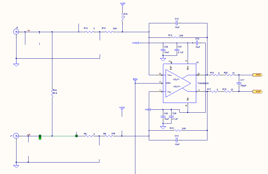
Prior to the test point, there is an AD744 operational amplifier with its output connected to a 10nF capacitor. Following this, a 1kΩ resistor connects to ground. From the junction where the capacitor and resistor meet, a 4.7kΩ resistor...
This simple amplifier is ideal for adding a headphone jack to equipment that lacks this feature. The Headphone Buffer circuit board is small enough (1.2" X 1.4") to squeeze into even the smallest spaces and power requirements are so...
This pyrometer is used to measure the temperature of an incandescent body. The principle behind this measurement is that the hotter the body, the spectrum of the emitted radiation will shift. A pyrometer is a non-contact temperature measurement device that...
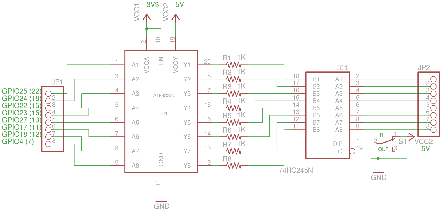
The current sourcing and sinking capability of the I/O pins on the Raspberry Pi is limited. According to the Wiki page, the current limit for each I/O block (for example, GPIO0 through GPIO27 combined) is only 26 mA maximum,...
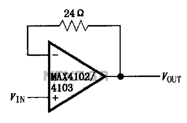
The MAX4102/4103 unity gain buffer circuit is illustrated in the figure. This circuit incorporates a small resistor (24 ohms) positioned in the feedback loop of the amplifier, which forms a unity gain buffer. Additionally, it achieves a maximum bandwidth...
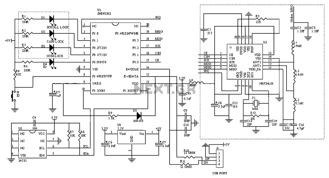
The circuit diagram for the receiving portion of a 2.4 GHz wireless keyboard is presented below. The 2.4 GHz wireless keyboard receiving circuit typically consists of several key components that work together to receive and process signals transmitted from the...
Warning: include(partials/cookie-banner.php): Failed to open stream: Permission denied in /var/www/html/nextgr/view-circuit.php on line 713
Warning: include(): Failed opening 'partials/cookie-banner.php' for inclusion (include_path='.:/usr/share/php') in /var/www/html/nextgr/view-circuit.php on line 713