
Leaky Transistor Buffer
The described wah pedal circuit is designed to be integrated into a guitar effects setup, primarily functioning to modulate the frequency response of the guitar signal. The initial issues encountered—low volume and scratchy sound—suggest potential problems with the transistor orientation or the grounding configuration. Transistors play a crucial role in amplifying the signal, and incorrect installation can lead to significant performance degradation.
In this case, the replacement of the transistor with an AC128 is a critical step, as this component is known for its favorable characteristics in audio applications. The increase in volume indicates that the transistor is now functioning to some extent, but the remaining issues with the fuzz effect suggest that the wah pedal's output stage may still be misaligned with the expected input of the Fuzz Face.
The identification of a positive ground circuit being incompatible with a negative ground setup is essential. Many effects pedals are designed with a specific grounding scheme, and mixing these can lead to operational failures. By reconstructing the circuit according to the negative ground schematic, the wah pedal can now properly interface with other effects and the amplifier, ensuring that the signal path is optimized for the best audio fidelity.
In a well-designed wah pedal circuit, the input stage typically includes a buffer to maintain signal integrity, while the wah effect is achieved through a variable bandpass filter controlled by the foot pedal. The output stage must be compatible with subsequent effects in the signal chain, such as fuzz or distortion pedals, which often have specific input impedance requirements.
For optimal performance, it is advisable to double-check all component orientations, ensure proper grounding, and verify that all connections are secure and free from solder bridges or cold joints. Regular maintenance and testing with an oscilloscope can help diagnose any further issues that may arise in the signal chain, ensuring that the wah pedal performs reliably in various configurations.The wah will work before the amplifier but sounds very low in volume and it sounds scratchy when the wah is rocked back and forth. The wah is fine without the buffer. In front of a fuzz face, with the fuzz face on, no sound passes Bizarre indeed. I`m going to go back to it and if I wired something wrong. Does the leakage and bias matter with the device Okay, I found part of the problem. I soldered in the transistor the wrong way, so, I removed it and put in a AC128. Unfortunately, I`m still having problems. There is an increase in volume but still no sound with the fuzz engaged, and it is still scratchy. I`m stumped. Ugh! Do I feel like an idiot. I realized that this is positive ground and won`t work properly in a negative ground circuit. I took it apart and rebuilt it using the proper schematic (negative ground) posted here at the beginning of this post. And, it works perfectly. 🔗 External reference
Related Circuits
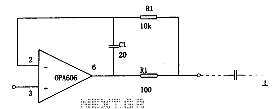
The isolation buffer circuit for capacitive loads is illustrated. When using an external operational amplifier (op-amp) with capacitive loads, the stability of the circuit is significantly affected, which leads to a degradation in dynamic performance. The circuit effectively demonstrates...
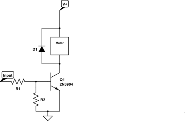
Control a small 5V motor using an external power supply by triggering a transistor with an Arduino. The transistor in use is an NPN type, specifically the 2N3904. To control a small 5V motor using an Arduino and an NPN...
The microphone has high sensitivity in the audio range, but in the ultrasonic range, the sensitivity decreases rapidly. The receiver is very sensitive. To prevent overdriving and feedback due to the high sensitivity of the microphone in the audio...
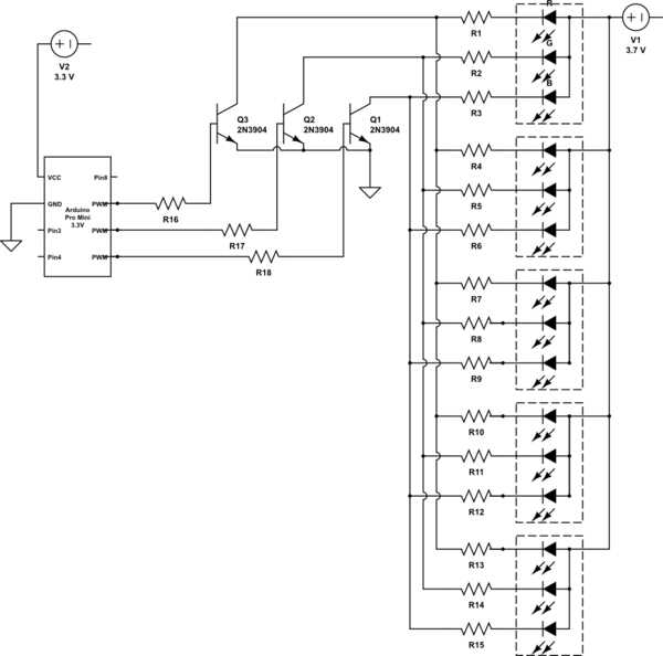
It is noted that the LEDs are not configured in parallel with the transistor. If they were, the LEDs would illuminate when the transistor is off. Instead, the LEDs are connected in parallel before entering the transistor. The transistor...
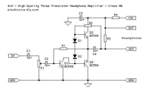
This is an improved version of a headphone amplifier I built many years ago. I wanted to share it because this simple circuit has done great service to me through all these years. It is very simple and reliable,...
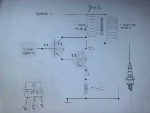
A request for assistance has been made regarding the development of a transistor ignition system to replace the point breaker in a motorcycle. The individual has researched extensively online but has not found a simple and effective circuit. The...