
Clap Switch Circuit using NE555 timer IC
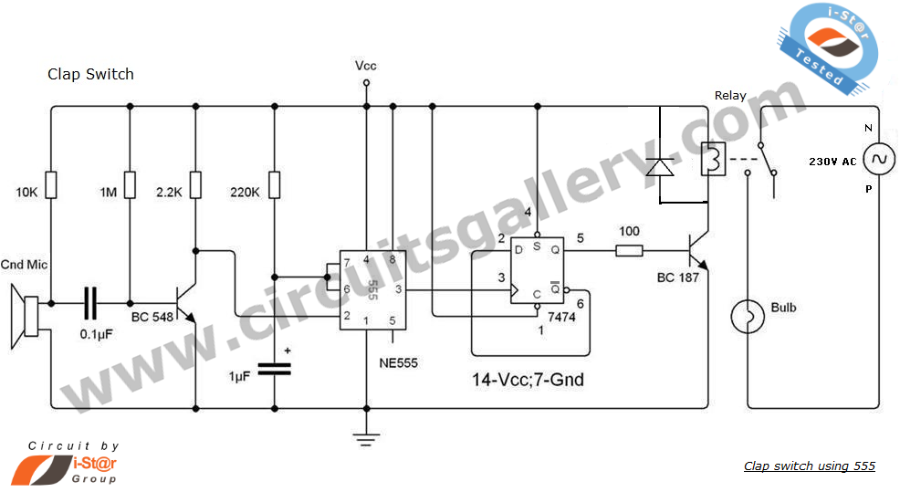
The clap switch circuit is a practical application of the NE555 timer and the 7474 D flip-flop, showcasing the interaction between sound detection and electronic switching. The NE555 timer is configured in a monostable mode, meaning it generates a single output pulse in response to an input trigger—in this case, the sound of a clap. The output pulse from the NE555 serves as a clock signal for the D flip-flop. The 7474 D flip-flop is designed to toggle its output state with each clock pulse it receives, effectively responding to the sound detected by the NE555 timer.
In operation, the NE555 timer detects a sound (such as a clap) and generates a negative pulse. This pulse is fed into the clock input of the D flip-flop, which is configured to toggle its output state on the falling edge of the clock signal. The first negative edge from the NE555 causes the output of the flip-flop to switch to a high state, while the next negative edge causes it to return to a low state. This toggling action can be used to control a relay, which in turn can switch on or off any connected electrical device, such as a light bulb or other appliances.
The circuit's versatility allows it to be used in various applications beyond just a clap switch, including sound detection systems and automated lighting controls. The relay acts as an interface between the low-power logic of the flip-flop and the higher power requirements of the connected devices, ensuring safe and reliable operation. Overall, this circuit exemplifies the principles of sound detection and electronic control, making it an excellent project for students and electronics enthusiasts.Here is one of the interesting 555 timer circuits to trick your friends while studying electronics in schools. Clap switch circuit is the local name of sound controlled flip flops. This sound controlled light can also be used as sound detection sensors. Flip flops are single bit storage elements. NE555 timer IC is the important part of this circuit . Here NE555 is configured in monostable multivibrator mode and is connected to the clock input of a 7474 D flip flop. The flip flop is connected to work in Toggle` mode. The relay circuit is energized by a 7474 flip flop. You can connect any electrical/electronic device at the output instead of the electrical bulb used here.
Below is the electronic circuit diagram and working of the clap light switch. Output of the 555 is connected to clock input of D-flip flop (IC 7474). It is a -ve edge triggered flip flop. When the Monostable output goes to zero, flop-flop`s output Toggles. That is (For time being consider flip-flop out is zero), for the 1st -ve transition output of the flip-flop goes to high and for the next -ve edge, output will be low. It will continue for successive -ve edges 🔗 External reference
Related Circuits
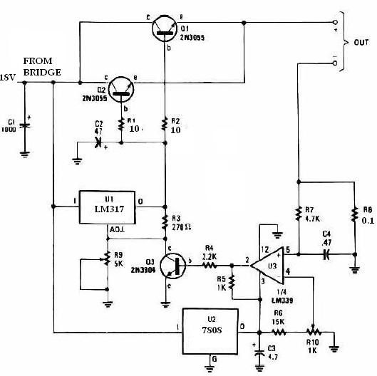
This universal battery charger utilizes the LM317 voltage regulator and features an adjustable output voltage along with a constant-current charging circuit, making it suitable for charging most NiCad batteries and various other battery types. The LM317 universal battery charger...
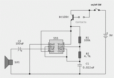
Probes or contacts may utilize a non-reactive metal. Gold or silver plated contacts from an old relay may be used; however, a cost-effective alternative is to wire alternate copper strips from a piece of veroboard. These will eventually oxidize,...
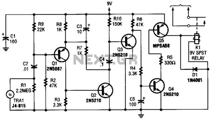
A GC Electronics P/N J4-815 transducer is utilized to receive 40-kHz acoustic remote-control signals. The receiver activates a relay to control another circuit. The GC Electronics P/N J4-815 transducer is designed specifically for the reception of 40-kHz acoustic signals, which...
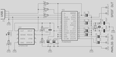
This is a high-quality preamplifier circuit with a built-in USB DAC designed for the Leachamp power amplifier. The schematic is derived from the PCM2902 datasheet. The circuit includes a DAC and ADC, SPDIF output and input, and an HID...
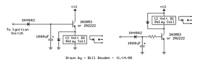
The two circuits illustrated show the operation of opening a relay contact shortly after the ignition or light switch is turned off. A capacitor is charged, and the relay remains closed until the voltage at the diode anode rises...
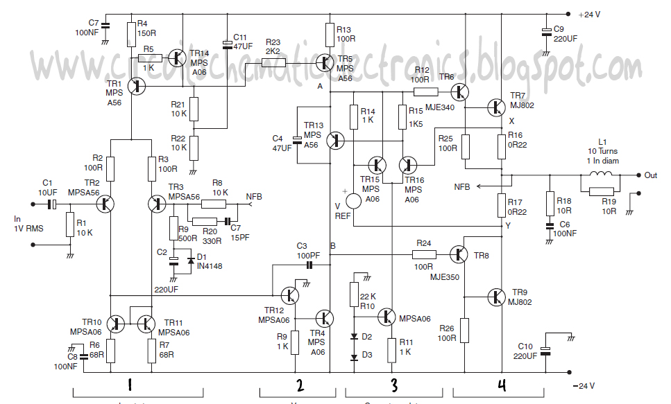
This design schematic represents a Class A power amplifier. It closely matches the operating parameters of Class B to facilitate comparison, particularly with a negative feedback (NFB) factor of 30dB at 20 kHz. The front end is similar to...