
A Master Control Unit for Receive Audio
The audio mixer system described is a versatile solution for managing multiple audio sources in a cohesive manner. The integration of a master Audio On/Off switch is essential for quick muting, enhancing user experience during interruptions. The ability to connect headphones at any of the three designated operating positions facilitates ease of use and minimizes cable clutter, which is particularly beneficial in environments where mobility is required.
The Master Control Unit's schematic design showcases a remote gain control mechanism that employs a 12-volt linear voltage regulator, ensuring stable operation across varying conditions. The linear taper potentiometer (R6) serves a critical role in allowing fine adjustments to the audio gain, with the FET providing efficient control over the audio signal path. This design ensures that only the active remote unit, selected through the Box Select switch, influences the overall gain, preventing conflicts between multiple units and maintaining clarity in audio output.
The physical construction of the enclosure, based on the Hammond 1590FF model, reflects a commitment to durability and functionality. The choice of paint and finishing techniques not only enhances the aesthetic appeal but also contributes to the longevity of the unit. The meticulous process of layout design using Visio ensures that all components are strategically positioned for optimal accessibility and usability. The drilling and painting process, while time-consuming, results in a professional finish that aligns with the standards expected in electronic equipment.
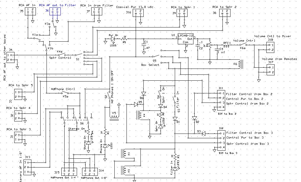
Overall, this audio mixer system is designed with user convenience and operational efficiency in mind, making it a valuable addition to any audio management setup.An audio mixer to which all the receiver audio outputs go, which is described here. The audio mixer`s output is amplified and drives a common speaker. So I hear all the radios (that are turned on) through that one speaker. This is fine as far as it goes. But. Sometimes I want to turn all the sound off without having to adjust the gain of each receiver - like when the phone rings. So I need a master Audio On/Off switch. I also want to be able to use headphones at any of three different operating positions. I want to be able to plug the headphones in at whichever operating position I am using so the cable isn`t strewn half way across the room. And, of course, I want to be able to switch the headphone audio On and Off. I wanted to put a block diagram of the system here, but I seem to have lost it. So we will have to live with just schematic diagrams. The schematic of the Master Control Unit is shown below. I won`t go into a lot of detail describing how it works because it`s pretty straightforward. The remote gain control is a bit interesting. This unit uses a 12 volt regulator, U1, to generate a regulated reference voltage (12 volts) which is applied to a linear taper potentiometer, R6.
The wiper of R6 provides a voltage that controls the gate of an FET in the audio mixer to set the overall gain of the mixer and, therefore, the system gain. Each of the Remote Units also has such a circuit. Only the unit that is in control, as selected by the Box Select switch, controls the gain of the system.
Below is a picture of the enclosure I used for this unit. It started life as a Hammond 1590FF (available from Mouser). This is the part number of an unpainted model, which is the one to get. The one I used was actually painted black, but I made do with what I had on hand. I sanded it down and painted it gray, using Krylon High Gloss paint, which I found at ACE Hardware. The part number of this paint is Krylon 1606 Pewter Gray Gloss. It`s actually pretty close to the color of the trim rings on Collins S line gear. But that`s not why I picked it. I picked it because I wanted a nice shade of gray that was light enough to provide good contrast for black lettering but not so light that it appeared to be a dirty shade of white. This color looks very electronic like a lot of military and industrial gear. I used Visio to lay out the front, back, and top panels. First I made a perimeter outline that is about the size of the panel. Then I made circles that approximated the profile of the perimeter of each component that mounts on the panel, including space for connections.
This allows me to space all the controls and connectors properly. Visio makes it easy to move these around until I get them all where I want them. Here`s the layout. The labels that will ultimately appear on the panels are not yet in their final form here. I print this out on paper and cut out each panel separately. I then tape the appropriate layout to the appropriate panel with masking tape, positioning it carefully using the outer perimeter as the main guide. When I`m happy with it, I use it as a drilling template to drill and punch all the holes. Once that is done, I paint the unit. I spray on four or five coats of paint, wet sanding in between coats with 1000 grit wet-or-dry sandpaper.
I just keep doing it until the finish passes my perfection filter - the width of which varies with time and mood. One of the tricks to getting a really good finish is to only spray horizontal surfaces. This requires spraying one side, letting it dry very well, rotating the unit so a different side is up, spraying the up side, and repeating until done.
It doesn`t take much actual labor time, but it takes a lot of elapsed time like a week. For me, it`s hard to 🔗 External reference
Related Circuits
This is a circuit for controlling the speed of small DC motors; it works nicely as a speed controller for an HO or N gauge model railroad. More: The left half of the 556 dual timer IC is used...
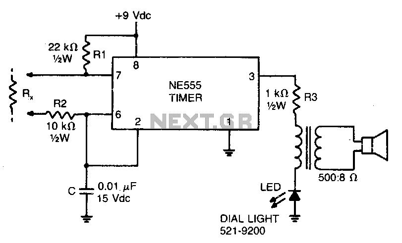
This low-current audio continuity tester indicates the unknown resistance value by the frequency of the audio tone. A high tone indicates a low resistance, while a tone of a few pulses per second indicates a resistance as high as...
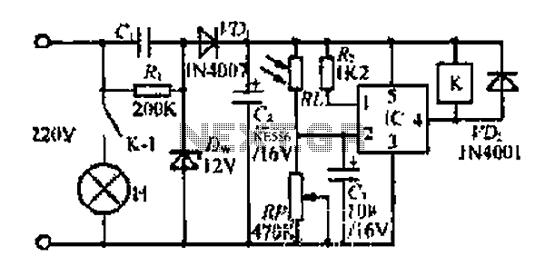
At dawn, light illuminates the photosensitive resistor RL, causing its resistance to decrease. This switch IC (2) exhibits a high electrical footprint. When light is present, the relay K does not activate. At night, in the absence of light,...
The example below illustrates the use of an operational amplifier (op-amp) as an audio amplifier in a basic intercom system. A small 8-ohm speaker is utilized as a microphone, which is connected to the op-amp input through a 0.1...
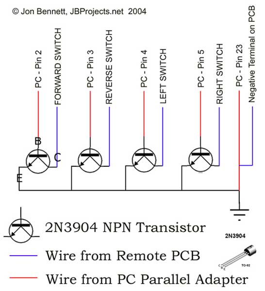
This project article was originally written in 2004 when most computers had parallel ports. This is no longer the case, so much of this information is now outdated. The Mini RC Car Project has been one of the most...
Schaer is a generic programmer circuit capable of uploading and downloading firmware to and from several electronic devices, such as microcontrollers. The Schaer programmer circuit is designed to facilitate the transfer of firmware between a host computer and various electronic...