
PWM DC Motor Speed Control

The described circuit utilizes a 556 dual timer IC, which contains two independent timer circuits. In this application, the left half operates as a square wave oscillator that generates a continuous pulse signal at a fixed frequency. The frequency can be adjusted by varying the resistor and capacitor values connected to this section, allowing for control over the motor's operational speed.
The output from the oscillator is directed to the right half of the 556, which is configured as a monostable multivibrator. This section is set up to stretch the width of the incoming pulse from the oscillator, effectively controlling the duration for which the motor receives power. By adjusting the timing components associated with the monostable configuration, the pulse width can be varied, thus controlling the average voltage supplied to the DC motor. This results in a variable speed control mechanism, allowing for smooth acceleration and deceleration of the motor.
The output of the monostable multivibrator can be connected to a transistor or a MOSFET, which acts as a switch to drive the DC motor. The choice of switching device will depend on the current requirements of the motor. Additionally, incorporating a diode in parallel with the motor can protect the circuit from back EMF generated when the motor is switched off.
This circuit is particularly suitable for model railroads, where precise control over motor speed is essential for realistic operation. The use of the 556 timer IC simplifies the design by integrating multiple functions into a single package, reducing component count and improving reliability.This is a circuit for controlling the speed of small DC motors, it works nicely as a speed controller for an HO or N gauge model railroad. The left half of the 556 dual timer IC is used as a fixed frequency square wave oscillator. The oscillator signal is fed into the right half of the 556 which is configured as a variable pulse width one-shot monostable multivibrator (pulse stretcher). The 🔗 External reference
Related Circuits
Since completing the degree in April, there has been a pursuit for employment. The search has been gradual, but there is optimism for future financial success. In the context of electronic schematics, the pursuit of employment can be likened to...
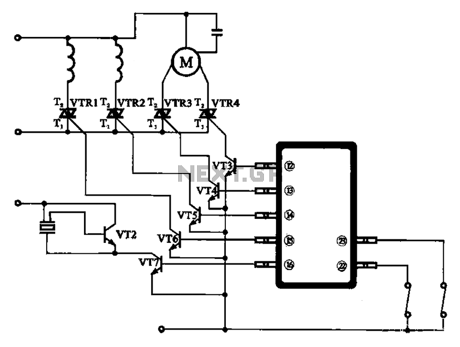
The schematic for the automatic washing machine motor driver outlines the motor drive circuit for the Narcissus XQB30-III-type washing machine. The control circuit comprises four Triacs, four drive transistors, and a control chip. This setup allows for the activation...
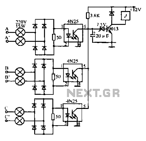
A, B, and C are used for a large power split-phase system. The A + BC range generator phase line features an A-A indole path string containing two 220V/15W bulbs. The bulbs recover based on macro instructions from J...
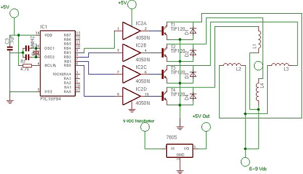
The primary motivation for utilizing battery power for trains is to eliminate the need for track cleaning and wiring. Track maintenance can pose significant challenges. Incorporating radio control into a battery-powered system enhances command control, an advantageous feature. In...
This circuit enables audio monitoring of a remote location, functioning as both a room monitor and a baby alarm. It can be powered by a 12-volt battery or a mains power supply. The interconnection utilizes three wires, allowing for...
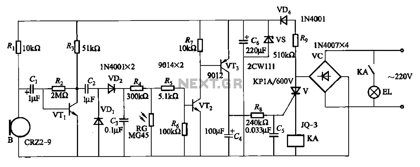
A resistor R8, capacitors Cd, and a thyristor V AC switch form a delay circuit. The lamp's lighting delay time is determined by the resistor Rs and capacitor C4, with a delay of approximately 40 seconds as indicated in...