
A muting delay & DC offset protection circuit
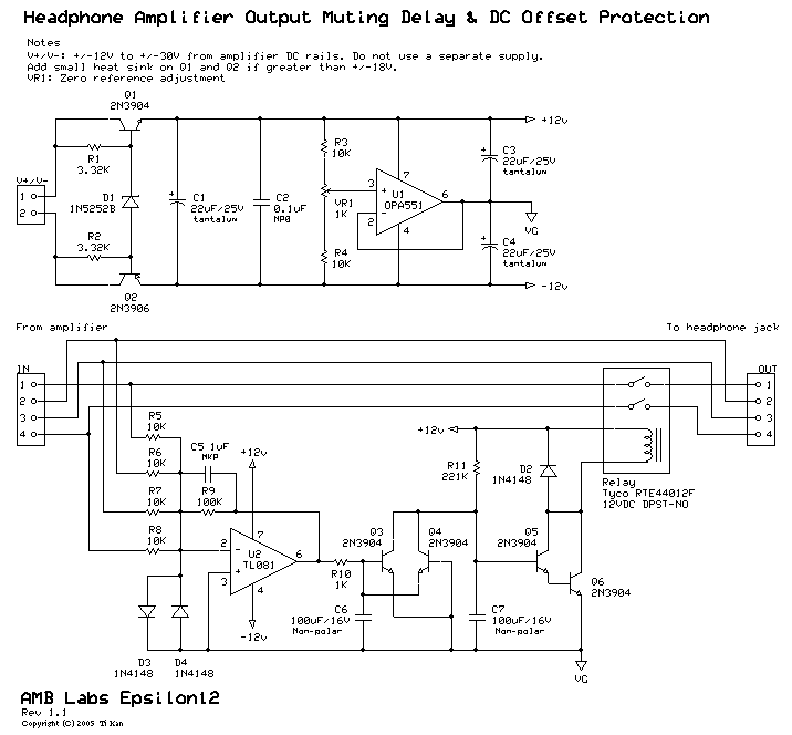
A low-pass filter functions by allowing signals below a certain cutoff frequency to pass through while attenuating frequencies above this threshold. This is particularly useful in audio applications where high-frequency noise can be filtered out, resulting in a cleaner signal. The phase shift introduced by the low-pass filter is frequency-dependent, meaning that different frequencies will experience varying degrees of phase delay. This property is crucial when integrating the filter with other audio components, such as headphones, to ensure that the output signal aligns correctly with the input signal at critical points, such as zero-crossings.
In practical applications, the implementation of a low-pass filter typically involves passive components like resistors and capacitors or active components like operational amplifiers. The design must consider the filter's cutoff frequency, which can be calculated using the formula \( f_c = \frac{1}{2\pi RC} \) for a simple RC low-pass filter, where \( R \) is resistance and \( C \) is capacitance.
When integrating a relay into the circuit, it is essential to account for its mechanical characteristics. The time delay in relay operation can introduce additional phase shifts in the audio signal, which may not be acceptable in high-fidelity applications. To mitigate these issues, designers often use electronic switching methods, such as MOSFETs or solid-state relays, which provide faster switching times and reduce the risk of contact bounce.
In summary, while a low-pass filter can effectively manage frequency responses in audio systems, careful consideration must be given to the integration of mechanical components like relays, as well as the overall design to ensure minimal disruption to the audio waveform.A low pass filter is merely a stable state-space system that has an input and spits out an output. If the input is a quasi-periodic signal, then the output would simply be the same quasi-periodic signal with a phase shift. Only difference would be that this system would have to transition from some initial condition (which would be ground, or the way you have it
which is in disconnection mode). I see what you`re trying to accomplish. Phase shift the signal so that when we reconnect the headphones it occurs at zero-crossing time to avoid the small discontinuity in waveform. Good thought, but. If you`re trying to make a phase shift in a uniform way with respective to frequency then you need an all-pass filter, not a low-pass filter.
But more to the point, you`ve got to remember that a relay is a mechanical device and it takes a small amount of time for the contact to close after energizing the coil. To do what you suggest here assumes that we know exactly when that is going to happen and, we don`t. And even if we did, transitioning from the phase-shifted version of the audio to the non-shifted version will still incur a small discontinuity in the waveform without doing something really fancy, and another relay is not going to cut it.
And relay contacts do "bounce" when closing, how would that affect the signal Actually, no. Trust me. Do a little measurement on your own. Hook up your DMM in AC milliamps mode in series with the connected ground, play a test tone and watch your meter and you`ll get a reading of some amount of current. Now, disconnect the positive side of both outputs. Still got a reading Static discharge is tens of thousands of volts or higher, arcing across air. Headphone amp DC offset is much smaller and cannot do that. Have a look at the schematics of almost any piece of audio equipment, and you`ll find that the power switch only switches one side of the AC line and there is no need to switch both.
Same principle - it breaks the circuit, and we`re talking about AC mains here, which is much higher voltage than any DC offset that this protection circuit is going to encounter. You`ve got to remember that a relay is a mechanical device and it takes a small amount of time for the contact to close after energizing the coil.
To do what you suggest he 🔗 External reference
Related Circuits
An LED is usually a series resistor needed to ensure that the LED does not get too much power. The disadvantage of such resistance is that the current through the LED and thus the brightness changes as the voltage...
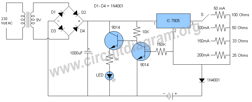
Schematic and description of a simple automatic NiMH battery charger circuit using IC 7805 with multiple selectable current options for charging. The described circuit is a straightforward automatic charger designed for Nickel-Metal Hydride (NiMH) batteries. It utilizes the IC 7805...
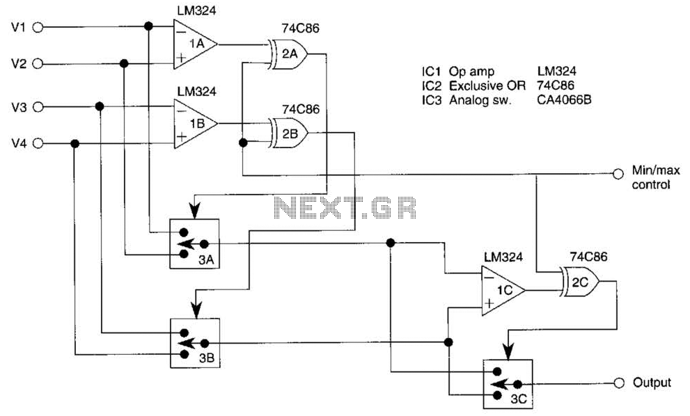
This circuit outputs the maximum or minimum of four input voltages, V1, V2, V3, and V4. Each of these input voltages ranges from 0 to 5 V. The output of the circuit is the maximum of V1, V2, V3,...
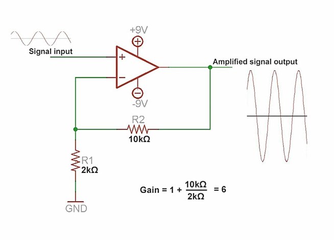
An amplifier is a device that increases the voltage in a circuit. The simplest type is an operational amplifier, and this video will demonstrate how these devices function and how to implement them in electronic applications. As an example,...
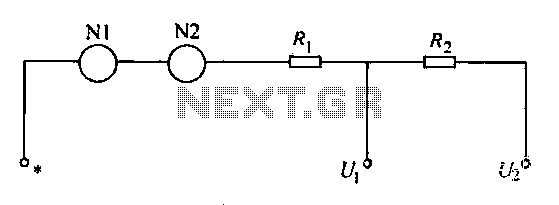
A voltmeter operates through a measuring mechanism in a specified circuit, utilizing a moving coil in series with additional resistance. The fixed coil is denoted as N1, while the moving coil is designated as N2. The additional resistances are...
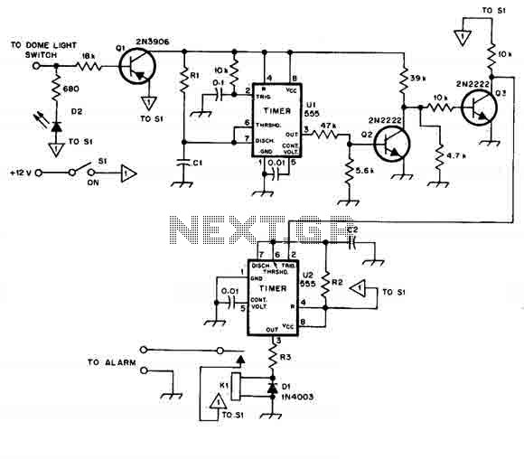
When this car alarm circuit is activated, it remains active for 80 seconds. There is a 15-second delay for the driver to enter and deactivate the alarm. All timings can be easily modified. The circuit utilizes two NE555 timers,...
Warning: include(partials/cookie-banner.php): Failed to open stream: Permission denied in /var/www/html/nextgr/view-circuit.php on line 713
Warning: include(): Failed opening 'partials/cookie-banner.php' for inclusion (include_path='.:/usr/share/php') in /var/www/html/nextgr/view-circuit.php on line 713