
amplify voltage and build microphone circuit
An operational amplifier (op-amp) is a high-gain voltage amplifier with differential inputs and typically a single-ended output. It is widely used in various applications, including signal conditioning, filtering, and mathematical operations. The fundamental characteristics of an op-amp include high input impedance, low output impedance, and the ability to amplify small voltage differences between its input terminals.
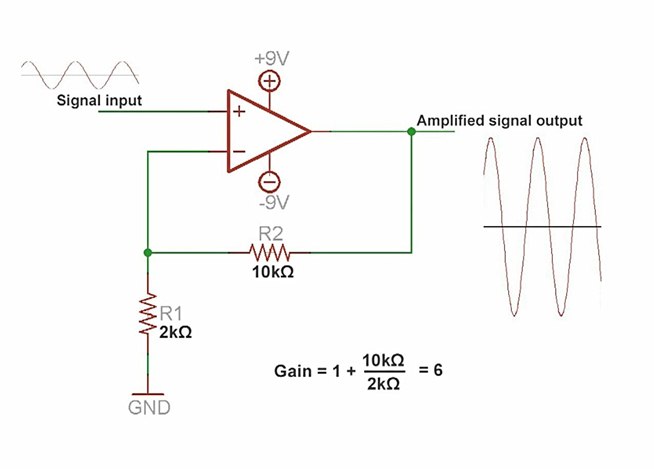
In the context of creating a microphone circuit, the op-amp can be employed to amplify the low-level audio signals captured by a microphone. The basic configuration involves connecting the microphone to the non-inverting input of the op-amp, while the inverting input is connected to a feedback resistor network that determines the gain of the amplifier.
A typical microphone circuit using an op-amp may include the following components:
1. **Microphone**: A condenser or dynamic microphone that converts sound waves into electrical signals.
2. **Op-Amp**: An operational amplifier configured in a non-inverting configuration for voltage gain.
3. **Resistors**: Feedback and gain-setting resistors that control the amplification factor.
4. **Power Supply**: A dual power supply (positive and negative) is often required to allow the op-amp to output both positive and negative voltage swings.
5. **Capacitor**: A coupling capacitor may be added to block DC components while allowing AC signals (audio) to pass through.
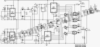
The circuit diagram for this microphone amplifier would illustrate the connections between these components, indicating the input from the microphone to the op-amp, the feedback loop created by resistors, and the output which can be fed into further processing stages, such as additional amplification or audio processing circuits.
This configuration not only amplifies the audio signals for better clarity and volume but also allows for the integration of additional features, such as filtering unwanted noise or integrating with digital systems for audio analysis. Proper attention to component selection and circuit layout is essential to minimize noise and distortion in the amplified signal.An amplifier is something that amplified the voltage on a circuit. The most basic kind is an operational amplifier, and this video will show you how these work and how to use them in your electronics. As an example you`ll learn how to make a microphone circuit for spying on people or listening to your heartbeat.
Circuit Diagram.. 🔗 External reference
Related Circuits
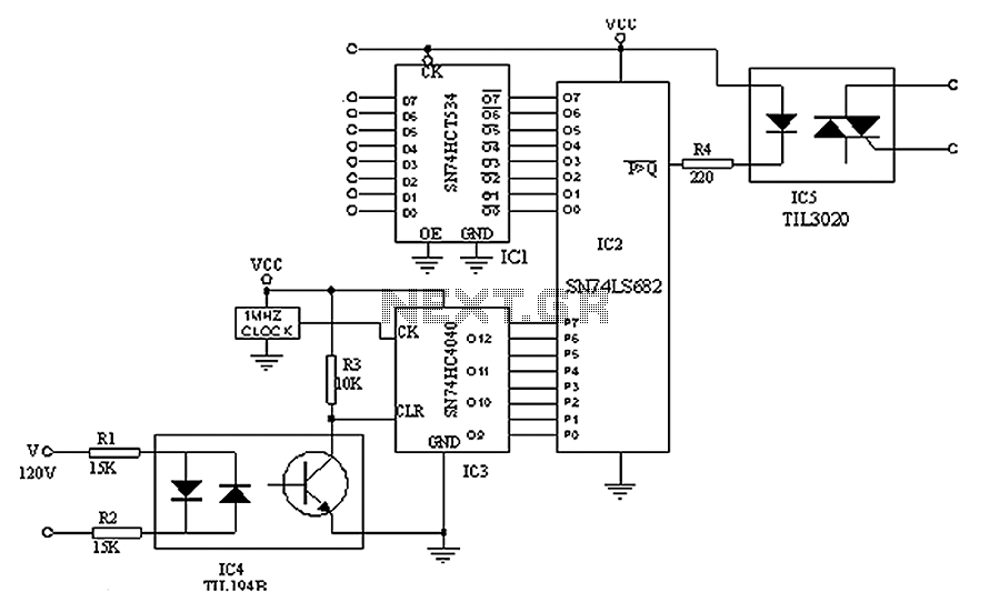
A simple digital circuit is presented that can be used to precisely control the AC power supply. This circuit does not include a digital-to-analog conversion component. In its application, effective control is established through a computer system that sends...
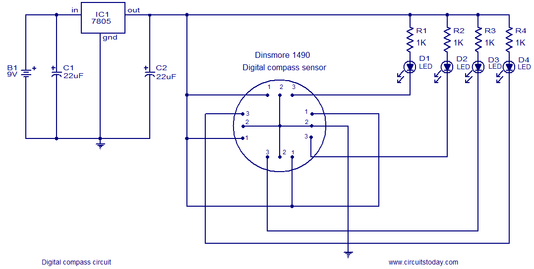
The following circuit illustrates a Digital Compass Circuit. This circuit is based on the 7805 IC. Features include a simple and accurate electronic compass. The Digital Compass Circuit utilizes the 7805 voltage regulator to provide a stable 5V supply necessary...
The L29 Stepper Motor Controller IC facilitates the control of four drive signals for two bipolar and four unipolar footfall motors in a microcomputer-controlled appliance. It allows for motor operation in half-step, full-step, and wave drive modes, utilizing switch-mode...
The following circuit illustrates an Automatic Room Power Control Circuit Diagram. This circuit is based on the NE555 integrated circuit (IC). Features include the use of two Light Dependent Resistors (LDRs). The Automatic Room Power Control Circuit utilizes an NE555...
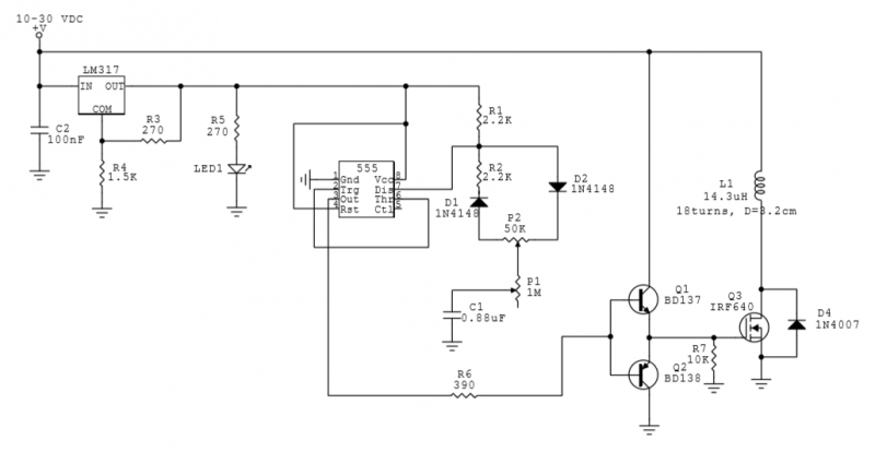
This circuit utilizes a 555 Integrated Circuit (IC) to generate a pulsed magnetic field, which can be employed for pulsed electromagnetic field (PEMF) therapy. The human body is affected by natural magnetic fields, including the Earth's magnetic field, geomagnetic...
The following circuit illustrates the SCR BRY35 used in a simple radio control circuit. Features include a straightforward and efficient receiver for operation. The SCR BRY35 is a silicon-controlled rectifier designed to facilitate the control of high-power loads through low-power...
Warning: include(partials/cookie-banner.php): Failed to open stream: Permission denied in /var/www/html/nextgr/view-circuit.php on line 713
Warning: include(): Failed opening 'partials/cookie-banner.php' for inclusion (include_path='.:/usr/share/php') in /var/www/html/nextgr/view-circuit.php on line 713