
Constant LED power circuit
The described circuit is a constant current source for an LED, utilizing two transistors (T1 and T2) and two resistors (R1 and R2). The primary objective of this configuration is to maintain a consistent current through the LED (D1) regardless of variations in supply voltage, thus ensuring stable brightness.
In this circuit, R1, with a resistance of 2.2 kOhm, is connected in series with the base of the first transistor (T1, BC 548B). This transistor acts as a current amplifier, controlling the base current, which in turn regulates the collector current flowing through the LED. The second transistor (T2, BD 137) is configured to further stabilize the current through the LED by providing feedback to the base of T1.
R2, with a resistance of 39 ohms, serves as a sensing resistor, allowing the circuit to monitor the current flowing through the LED. This feedback mechanism is crucial, as it ensures that any changes in voltage do not affect the LED's brightness. The circuit is designed to operate efficiently within a voltage range of 5 to 24 volts, making it versatile for various applications.
When the circuit is powered, the voltage drop across R2 is monitored. If the current exceeds a predetermined threshold, the resulting voltage drop will reduce the base current to T1, causing it to lower the collector current. This negative feedback loop effectively stabilizes the LED current, ensuring consistent illumination.
In summary, this circuit design is an effective solution for driving LEDs with a constant current, mitigating the effects of voltage fluctuations and enhancing the reliability of LED performance in various electronic applications.An LED is usually a series resistor needed to ensure that the LED does not get too much power. The disadvantage of such resistance is that the current through the LED and thus the brightness changes as the voltage changes. This circuit prevents, through independent of voltage, constant current through the LED control. The circuit uses two transistors and two resistors. The circuit can be connected to voltages from 5 to 24 V. R1 = 2.2 kOhm R2 = 39 ? D1 = LED T1 = BC 548B T2 = BD 137 🔗 External reference
Related Circuits
The principle utilized in this electronic head or tail circuit is straightforward: a multivibrator controls a flip-flop. The multivibrator oscillates as long as the button S1 is pressed, while the flip-flop toggles on and off at a frequency of...

Figure 4-33 illustrates a circuit configuration that includes a common amplifier along with analog inductive circuits. In this setup, the transistor in the analog inductive circuit is utilized, and an increase in the bias resistor enhances circuit stability. A...
This project is used as an electronic private exchange. It has two telephones, which have the intercom facility, and they can be connected to the telephone line. All the functions are controlled by the 8-bit microcontroller AT89C2051 which has...
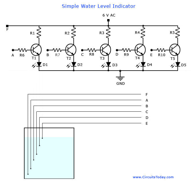
A simple water level indicator project with a circuit diagram for home and industry. This water tank level sensor can be utilized for any liquid level indicator projects. The water level indicator circuit is designed to monitor and display the...
This circuit is a motion detection sensor that utilizes a light source and detector as an infrared motion detector. The motion sensor employs an infrared LED and a phototransistor. Since it relies on light, the sensor's sensitivity can be...

The IR Jammer is a fun project that provides a bit of safe, non-destructive fun. The Infrared Remote Control Jammer allows you to render all IR remote controls inoperative! The microcontroller in this design allows for all 6 of...
Warning: include(partials/cookie-banner.php): Failed to open stream: Permission denied in /var/www/html/nextgr/view-circuit.php on line 713
Warning: include(): Failed opening 'partials/cookie-banner.php' for inclusion (include_path='.:/usr/share/php') in /var/www/html/nextgr/view-circuit.php on line 713