
A Ph Probe Buffer Amplifier
The buffer amplifier serves a critical role in interfacing high-impedance sensors, such as pH probes, with lower-impedance measurement devices or circuits. The high input impedance of the buffer amplifier ensures that the probe's output signal is not significantly affected by the load it drives. This characteristic is crucial when dealing with the delicate signals produced by pH sensors, which can be influenced by external factors if connected directly to measurement equipment.
The typical configuration of a buffer amplifier utilizes an operational amplifier (op-amp) in a voltage follower arrangement. In this setup, the output of the op-amp is connected directly to its inverting input, while the non-inverting input receives the signal from the pH probe. This configuration provides unity gain, meaning that the output voltage will be equal to the input voltage, effectively allowing the buffer to pass the signal without amplification or attenuation.
To ensure optimal performance, it is important to select an op-amp with a very high input impedance, low output impedance, and a wide bandwidth. This will help to maintain signal integrity and minimize any potential distortion or noise introduced by the amplifier. Additionally, power supply considerations should be taken into account to ensure that the op-amp operates within its specified voltage limits, which can vary depending on the specific application.
In practical applications, the buffer amplifier may also incorporate additional features such as filtering or gain adjustment, depending on the requirements of the measurement system. However, the primary function remains focused on isolation and impedance matching, providing a reliable interface between the pH probe and subsequent processing or display circuits.Buffer amplifier is required by a typical pH probe to isolate its 10^6 to 10^9 ohm source resistance from external circuitry. Such an amplifier is shown in the.. 🔗 External reference
Related Circuits
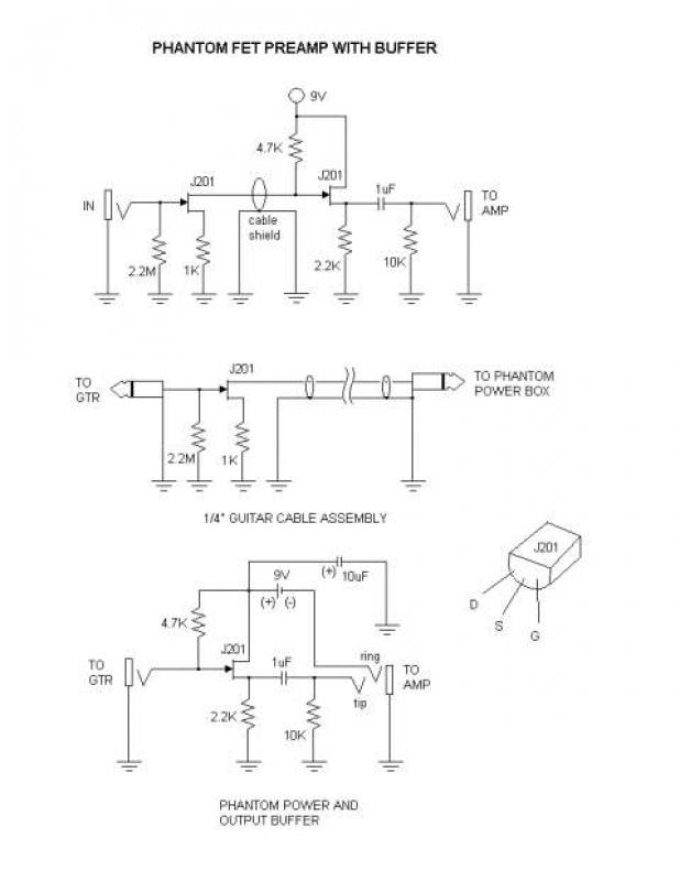
This is a phantom-powered FET preamplifier integrated into a 1/4" guitar cable, similar to the design found on the Tillman site. The amplifier consists of only a few components, making it challenging to trim and solder the leads to...
The JBL "Bass Wave" amplifier is a compact 100-watt amplifier featuring a built-in active filter that includes a single-pole high-pass filter at 10 Hz and a single-pole low-pass filter at 85 Hz. Priced at an affordable $50 USD, it...
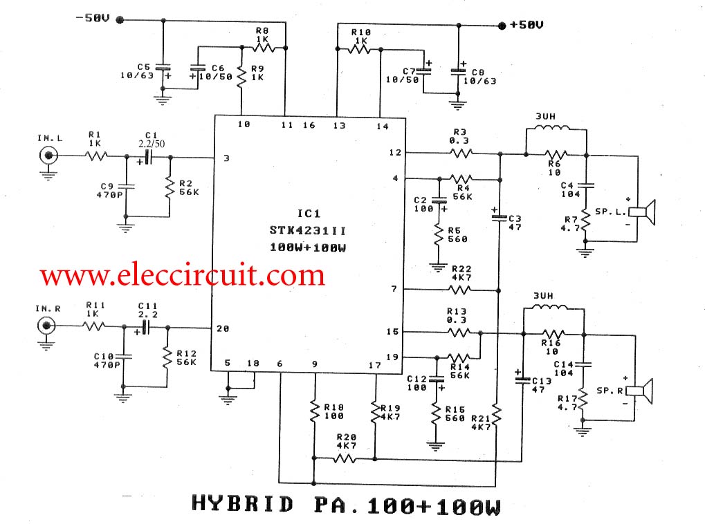
To create a 100-watt OCL audio amplifier circuit, consider using this design. It incorporates the STK4231 integrated circuit, which is a compact and cost-effective solution. The STK4231 is a hybrid IC from Sanyo, belonging to the STK4201II series, capable...
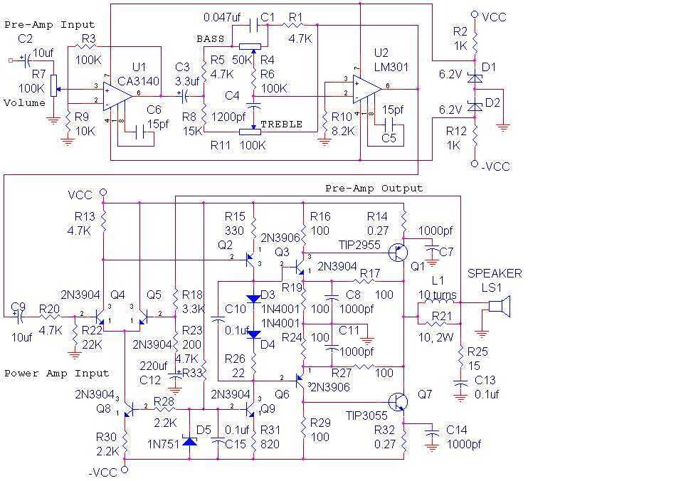
The audio amplifier shown below provides 14 watts of power, but can provide much more simply by increasing the power supply voltage. This amp was built in 1975 and has worked reliably ever since. The power amp portion was...
Since I have provided the schematic for John L Linsley-Hood's Class-A amplifier, I felt that some readers may wish to experiment with the concept. Unfortunately, a very low ripple power supply is needed for all Class-A amps, and the...
The described shunt-feedback configuration facilitates the straightforward incorporation of frequency-dependent networks, enabling a practical and unobtrusive switchable tilt control as an optional feature. When switch SW1 is in the first position, a gentle shelving bass boost and treble cut...
Warning: include(partials/cookie-banner.php): Failed to open stream: Permission denied in /var/www/html/nextgr/view-circuit.php on line 713
Warning: include(): Failed opening 'partials/cookie-banner.php' for inclusion (include_path='.:/usr/share/php') in /var/www/html/nextgr/view-circuit.php on line 713