
Pure Class-A Headphone Amplifier Schematic
The shunt-feedback configuration is a versatile circuit design commonly used in audio applications to manipulate frequency response characteristics effectively. This setup typically involves an operational amplifier (op-amp) in a feedback loop, where the feedback network can be adjusted to influence the gain and frequency response of the circuit.
In this specific configuration, the integration of frequency-dependent networks allows for the implementation of a tilt control feature. This control can be particularly useful in audio processing, as it enables the user to adjust the tonal balance of the output signal without significantly altering the overall gain of the system. The optional nature of this feature ensures that it can be included or excluded based on the specific requirements of the application.
The switch SW1 serves as a user interface for selecting different tonal adjustments. In the first position, the circuit is designed to provide a gentle shelving bass lift while attenuating the treble frequencies. This setting can enhance the warmth of the audio signal, making it suitable for bass-heavy music genres or environments where a fuller sound is desired.
The central position of SW1 maintains a flat frequency response, ensuring that the audio signal remains unaltered. This is essential for applications requiring accurate sound reproduction, such as in studio monitoring or critical listening environments.
In the third position, the circuit configuration shifts to provide a shelving treble boost while cutting the bass frequencies. This adjustment can be advantageous in situations where clarity and brightness are necessary, such as in vocal performances or when emphasizing higher frequency instruments.
Overall, the shunt-feedback configuration with the integrated switchable tilt control offers a flexible solution for audio signal processing, allowing users to tailor the frequency response to suit various listening preferences and environments.The mentioned shunt-feedback configuration also allows the easy addition of frequency dependent networks in order to obtain an useful, unobtrusive, switchable Tilt control (optional). When SW1 is set in the first position a gentle, shelving bass lift and treble cut is obtained. The central position of SW1 allows a flat frequency response, whereas the third position of this switch enables a shelving treble lift and bass cut..
🔗 External reference
Related Circuits
The power supply has been simplified. Power transformers and rectifiers have been omitted, and some components from the MOSFET voltage regulator circuits have been removed, including 1N5242 zener diodes between the source and gate and 10k resistors in series...
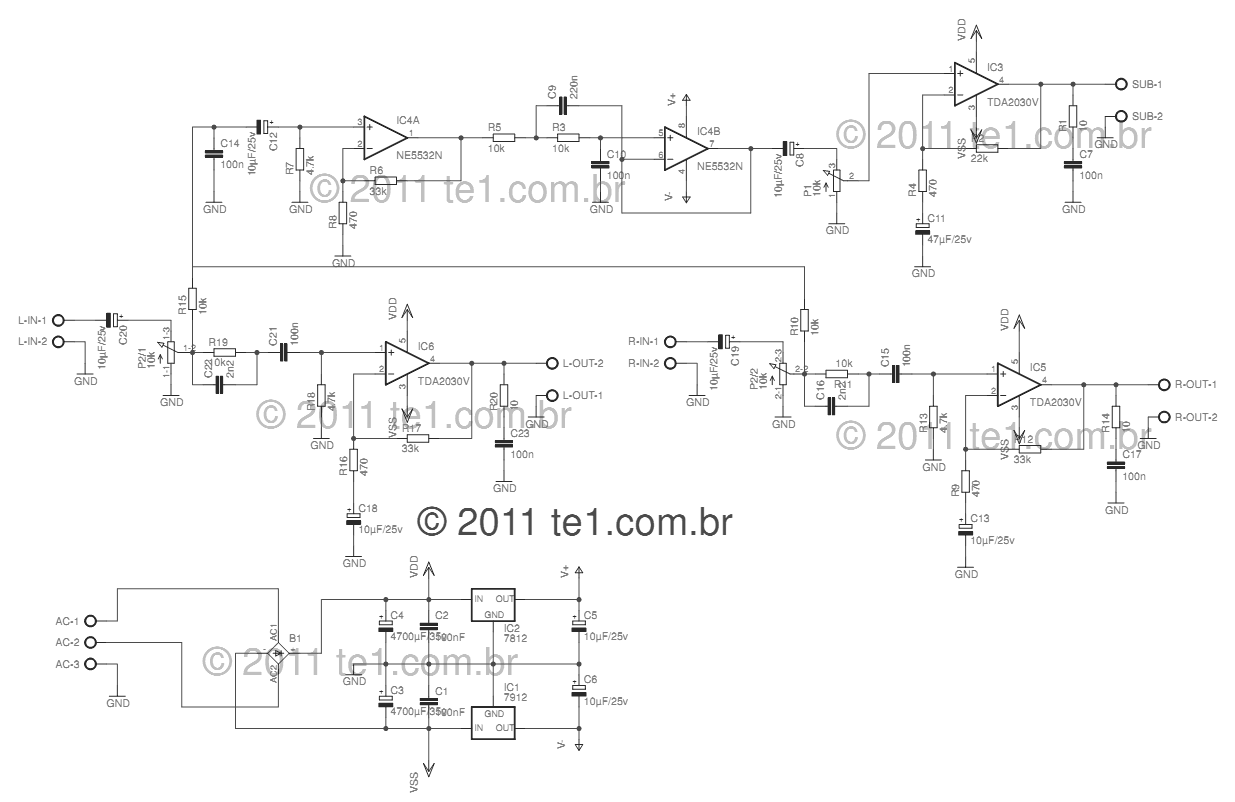
This circuit is a complete application for a 2.1 amplifier system, consisting of two satellite speakers powered by a TDA2030 and one subwoofer. This 2.1 system is commonly utilized in commercial applications as an amplifier for computers, enhancing audio...
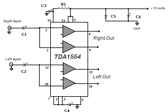
A 22 Watt stereo amplifier circuit diagram is presented. This circuit can be utilized for audio home amplifiers as well as car audio amplifiers. It features a straightforward design, is cost-effective, and is very easy to assemble, making it...
The circuit diagram of a guitar preamplifier is designed to accept any standard guitar pickup. This preamplifier is versatile, featuring two signal outputs. A typical configuration involves a pickup attached to the guitar headstock, where the pickup device consists...
This circuit design features a modular arrangement that enables users to select only the modules best suited to their needs, allowing for the construction of a chain ranging from one to five modules in length. For those seeking a...
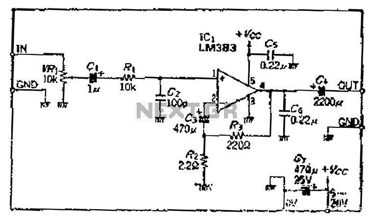
A closed-loop amplification circuit is designed to achieve a magnification of 100 times (40 dB). To ensure stable operation, particularly with high input signals, a variable resistor (VRi) is incorporated in the secondary circuit for attenuation. The feedback resistor...