
Basswave amplifier
The schematic of the JBL "Bass Wave" amplifier comprises several key components that work together to deliver its functionality. The amplifier begins with a low-pass input network that filters incoming audio signals before they reach the main amplifier stage. The main amplification is handled by an LF347 operational amplifier, which is known for its high gain bandwidth product and FET input characteristics, making it suitable for audio applications. This op-amp drives a modified Darlington configuration that acts as a current amplifier, enhancing the overall output capability while also providing voltage gain.
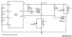
The output stage utilizes TIP31C and TIP32C transistors, which are configured to work in tandem without emitter resistors, leading to potential crossover distortion. The design features a thermistor for thermal management, providing a safety mechanism that shuts down the amplifier if the temperature exceeds safe limits. The absence of short-circuit protection necessitates caution during operation, particularly when driving lower impedance loads.
For those considering modifications, the proposed enhancements focus on increasing the amplifier's robustness and performance. Suggestions include upgrading the power supply components, such as rectifiers and filter capacitors, to improve current handling capabilities. Additionally, the introduction of emitter resistors in the output stage would facilitate better current sharing among the transistors, mitigating distortion and improving overall sound quality. These modifications, while promising, require careful implementation and testing to ensure stability and reliability in the amplifier's operation.The JBL "Bass Wave"amplifier is a small 100-watt amplifier with built-in active filter with a single-pole high-pass at 10 Hz combined with a single-pole lowpass at 85 Hz. It costs an amazingly low $50 US. It also comes with line and speaker-level inputs and a volume control for level-matching, and an "auto signal sensing power switch".
It also fea tures reasonable build quality. However, it is not an "audiophile" or even hifi-quality amplifier - a few corners have been cut in the design inorder to keep the price so low. However, it may be possible to improve it a bit with a few tweaks. The Bass Wave amplifier uses a "class-B" output stage. Most audio amplifiers use a "class-AB"output stage because class-B circuits are prone to crossover distortion, which audibly affects the output at low volumes.
The notch distorion may show as a fuzziness or raspy character at very low levels. Note that this is of less consequence in a subwoofer design, as the effect is less noticeable at low frequencies, and how many times have you listened to a subwoofer at low volumes The output devices in the Bass Wave amplifier are used in a common collector configuration. While this raises the voltage gain of the stages (and is a cheap way to save parts), it also raises the output impedance, which in turn reduces the current dumping and damping factor of the amplifier.
The voltage gain should come from the driver stage of the amplifier, not the output devices. (Correction - Jason Cuadra says that it is a composite 2 stage common emitter with local feedback set by R31 and R30, setting gain to 10). Bill Wilson of the DIYLoudspeakers List described the circuit design of the Bass Wave amplifier as follows in message to the List (which I`ve edited slightly here): " A low pass input network feeds the main amplifier which is a LF347 op amp driving a modified darlington current amplifer which is wired to also give voltage gain.
The LF347 is a nice op amp with gain bandwidth product of 4 Mhz and FET inputs. There is no quiescent current biasing of the output transistors. The bases of the 1st stage output transistors (TIP31C and TIP32C) are copper bound to each other giving 1. 2 volts of crossover distortion. There are no emitter resistors anywhere, not even in the 2nd stage TIP35C/TIP36C emitters. As far as driving 4 ohms go, the TIP35C/TIP36C transistors have the current rating to handle this but I don`t know about the power supply.
There are 4700uF capacitors filtering the rectified DC and I would want to load test the transformer before feeling safe about it. There is a thermistor on the heat sink wired to an op-amp comparator which will shut the amp down at some temperature, but note that there is no short circuit protection on the output transistors.
There is an audio signal detection circuit that drives the front panel LED, but the power amp insided is not powered down, just the LED. " Listed below are some modifications to the amplifier that have been PROPOSEDby members of the DIY Loudspeakers list.
These modifications have not actually been tried out, but they do sound good enough for consideration: Jason Cuadra : "To increase output current capability, double up the filter caps, change to beefier rectifiers. ( a la 5A 200V ) and double the output transistors(in parallel), but with an emitter resistor for each one of about 0.
1 ohm, to make them share current. To bias it into class AB would require re-designing the whole stage: - It would require an additional 2 power resistors, 2 smaller resistors, 2 constant current sources each made of 2 transistors and a resistor, and a VBE multiplier stage made of a transistors and 2 resistors; reducing the gain of the output stage (from 10 to 3 or 4), and re-checking the feedback loop stability. " This is a circuit showing some of the some mods I talked about, with the addition of current limiting / short cct protection, and this is another circuit show
🔗 External reference
Related Circuits
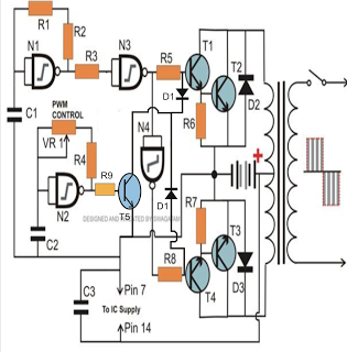
The PWM-controlled modified sine wave inverter circuit presented here utilizes a single 4093 integrated circuit (IC) for its specified functions. This IC consists of four NAND gates, with two configured as oscillators and the other two serving as buffers....
Circuit stereo TDA2822 audio power amplifier circuit schematics. In this series, the TDA2822M IC is utilized as the primary amplifier. Additionally, alternatives such as KA2209 and NJM2073 can also be employed. The TDA2822 audio power amplifier circuit is designed to...
To design a Tube Headphone Amplifier we need a triode with uncommon characteristics: enough voltage gain, low internal resistance and good anodic current. My first test was done with the E182CC, but there is the limitation on the usable...
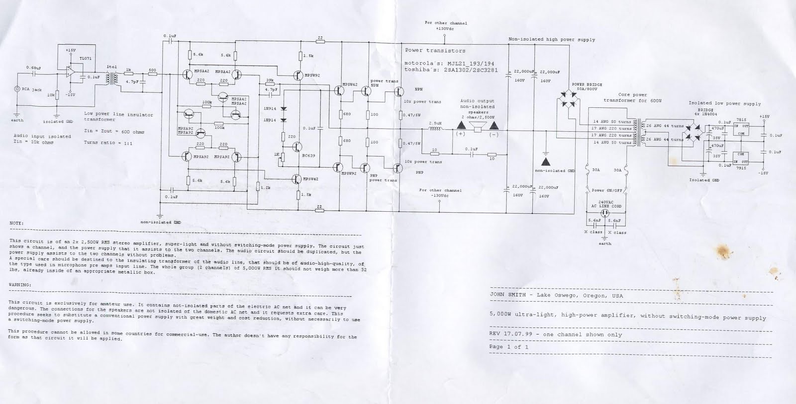
This device is a 2x2, 500W RMS stereo amplifier, designed to be super-lightweight and equipped with a switching-mode power supply. The device features a single channel display and specifies the power output it provides to both channels. The audio...
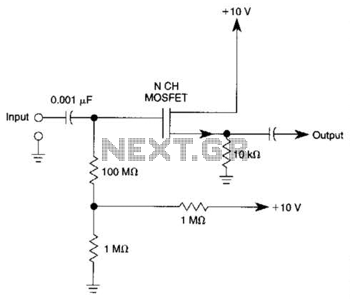
Biasing methods for an N-channel MOSFET to form a unity-gain noninverting amplifier or source-follower. The N-channel MOSFET can be utilized in various configurations, with one common application being the unity-gain noninverting amplifier, also known as a source-follower. In this configuration,...
The circuit presented is a straightforward yet efficient amplifier that can provide notable performance enhancements. This amplifier can demonstrate negative resistance at lower settings of the 500-ohm potentiometer, resulting in increased gain or even oscillation. Consequently, the circuit can...