
A Regenerative Receiver with AGC for 80 Meters or 3-10 MHz Shortwave

The Regenerative Receiver operates by utilizing a regenerative circuit that amplifies incoming radio frequency signals while maintaining sensitivity and selectivity. The design incorporates a low-noise RF amplifier, which serves to buffer the antenna input and prevent variations in the antenna's impedance from affecting the regenerative detection process. The use of a 2N3904 transistor in the front-end stage enhances the receiver's ability to isolate the detector from external influences, thereby stabilizing the oscillation frequency.
The tuning mechanism is a critical aspect of this receiver, allowing users to adjust frequency settings precisely. The combination of a PCB trim capacitor and varactor diode tuning enables a broad tuning range, accommodating various shortwave frequencies. The addition of a bandpass filter is advisable to further refine the signal quality, particularly for users operating in crowded frequency environments.
Future iterations of the receiver are expected to incorporate a zener diode regulator to mitigate frequency drift, which is a common challenge in regenerative circuits. This regulator will enhance the overall stability of the receiver, providing a more reliable listening experience. The inclusion of an audio amplifier and speaker will eliminate the need for external amplification, streamlining the user experience.
The S-Meter circuit, which is designed to provide visual feedback on signal strength, will be refined in subsequent versions to ensure accuracy and reliability. The potential development of a switched crystal converter would allow for multi-band operation, significantly increasing the versatility of the receiver.
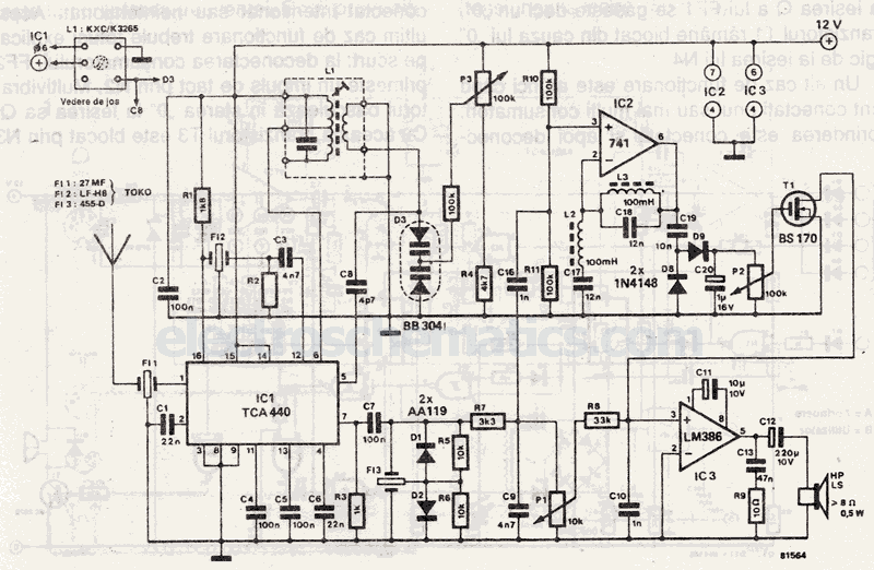
Overall, this Regenerative Receiver project exemplifies a careful balance between sensitivity and stability, making it a valuable tool for amateur radio enthusiasts and shortwave listeners alike.Here`s a Regenerative Receiver project that I designed for the 80 meter Amateur band, but which can also be used in a wider-tuning configuration that covers approximately 3 MHz to 10 MHz, for Shortwave (World Band) listeners. Built in the same style as my previous "40-Meter Tweeter" which can also be found at my Radio Projects menu at, this radi
o features: * 3-10 MHz tuning set by pc board trim capacitor, but main panel bandspread via varactor diode tuning which is renamed Main Tuning and covers a band of frequencies variable to 150 KHz from where the pc board trimmer is set * Low input impedance matches 50 ohm antenna system - giving relatively little AM overload/bleedthrough (although you may want to add a 3. 8 MHz bandpass filter after the antenna jack and input diodes; see text and schematic below). This is version 1 of this design, so it is to be expected that there will be some modifications, especially as I get feedback from other builders who try the circuit out for themselves.
Other features that I will probably include in the next version of this basic 80 M regen are: * I may add a zener diode regulator - So far, the 80 M prototype drifts in frequency very slightly; not nearly as much as the 40 meter version did, which absolutely required a zener regulator * A built-in audio amplifier and speaker. Right now there is a headphone jack, which I am running into a Radio Shack amplified speaker (they still have `em!
Get `em while they`re hot and not-yet-discontinued! $12. 99 last I checked) * An S-Meter circuit. I actually designed one with the AGC included in this radio, but had some problems with the "zeroing" of the meter tending to drift off zero after a while - so I left it out of this first version and plan to include it in the next, when the bugs are worked out * I will probably build a switched crystal converter for the front end of this design and make the radio into a Regenerodyne multi-band. Have not built a Regenerodyne yet but it is a wonderful idea and could make for a simple, basic station receiver Though I built the entire radio on a piece of 5x7", double-sided copper-clad pc board (from Radio Shack), with front panel and partial sides and back, (see photos at bottom), I decided to break the schematic up into 3 sections for easier analysis, below.
First, the "front-end". Built around Q1, a common 2N3904 NPN silicon transistor, we have an RF amplifier/buffer to keep the regenerative detector isolated from the antenna. Regen builders are aware that a swaying antenna on a windy day can cause the oscillating detector frequency to sway also, which of course is very annoying.
On top of that, the oscillating detector is actually transmitting its signal out the antenna and causing potential interference. This front-end RF stage keeps that from happening. I am able to verify that this stage isolates the detector pretty well in that I have an ATU (Antenna tuner or Transmatch) connected between the external antenna and the receiver.
With no isolation, the regen can be detuned by turning the ATU knobs back and forth around the resonant spot on the ATU. With Q1`s circuit in place, hardly any frequency shift occurs. Now as far as gain or amplification is concerned, we home-builders always assume "the more, the better".
I have learned that this is not always the case - especially with regens. Regenerative circuits are already extremely sensitive, which means that if you shout in their ears, their little eardrums are going to hurt (overload). A problem I`ve often encountered is what is known as "blocking" - when a very strong signal overloads and swamps the detector, being stronger than the oscillator "injection level" of the detector itself.
So the detector`s frequency is "pulled" and it tends to "lock onto" the incoming signal, sometimes stopping oscillation altogether. [We`re assuming that we`re in a ham band listening to CW or SSB voice here, which require 🔗 External reference
Related Circuits
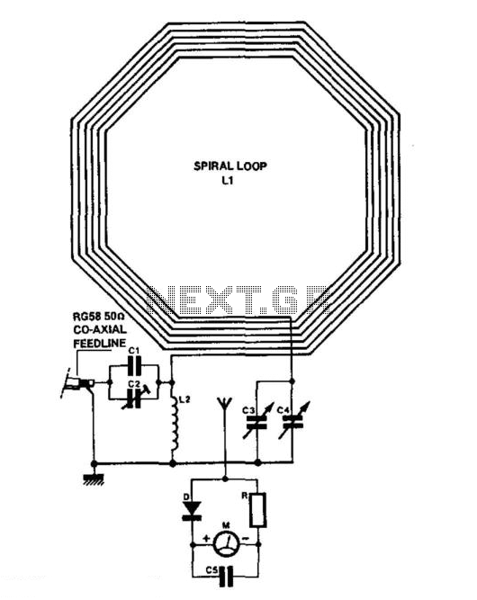
The receiver consists of multiple subassemblies, including an active antenna, an amplifier featuring regeneration control and band-switching circuitry, an AM detector, a power amplifier, and an output device such as an internal speaker, external speaker, or headphones. Additionally, it...
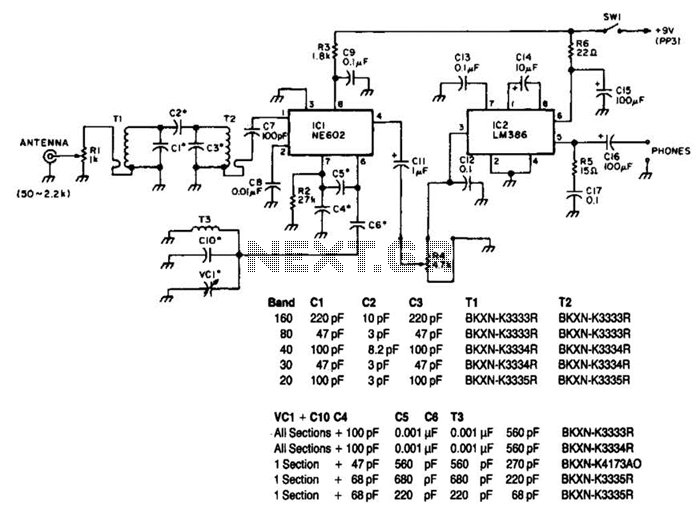
Note that T1 and T2 are TOKO components, including part numbers for the coils T1 and T2. The direct-conversion receiver shown utilizes a double-tuned input network made from readily available TOKO coils. IC1, an NE602, serves as a voltage-controlled...
The purpose of this project is to build a simple receiver for 50MHz. The receiver is built around the circuit MC3372, which is a narrow band FM receiver. The receiving frequency can be set with an LC tank or...
C1 = 3750 pF 500 V silver-mica capacitor. C2 = 100 pF preset capacitor (Jackson C803). C3 = 75 pF variable capacitor (Jackson C809) with a knob. C4 = 12.7 pF variable capacitor (Jackson C16) with a knob. C5...
Narrow Band Frequency Modulation (NBFM) is utilized in this 27 MHz transmitter circuit schematic. This circuit is based on the Motorola MC2833 VHF transmitter, which integrates FM modulation and narrow band capabilities into a single chip. P1 is designated...
A simple CATV upstream fiber optic receiver utilizes DC pilot automatic gain control (AGC). Upstream fiber links in a community antenna television (CATV) system are often challenging to align correctly. Set-top boxes and cable modems use "long-loop" AGC. Additionally,...