
Loop Antenna For 3.5 Mhz
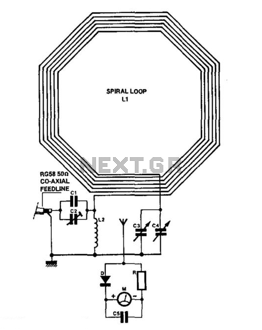
The schematic incorporates a variety of components that contribute to the functionality of the loop antenna design. The capacitors (C1 through C5) serve various purposes, including tuning and impedance matching, which are critical for optimizing the antenna's performance across the desired frequency range. The silver-mica capacitor (C1) is particularly valuable for its stability and low loss at high frequencies, while the preset (C2) and variable capacitors (C3 and C4) allow for fine-tuning of the antenna's resonance.
The moving coil meter (LB808) provides visual feedback on the antenna's performance, enabling the user to monitor the standing wave ratio (SWR) or power levels. The HF silicon diode (D) serves as a rectifier or detector, allowing for signal processing within the circuit. The resistor (R) is included for current limiting or biasing, ensuring that the circuit operates within safe parameters.
Inductors L1 and L2 are designed to create the necessary magnetic fields for resonance. L1, constructed from PVC-covered stranded wire, is designed for high voltage and current handling, while L2, made from tinned wire, provides additional inductance to the circuit. The RG58 coaxial cable serves as the feedline, connecting the antenna to the transmitter and minimizing signal loss.
The enclosure is constructed from an ABS box, providing durability and protection for the internal components. The terminal blocks facilitate easy connections for wiring, while the insulated spacers ensure that components are securely mounted and electrically isolated where necessary. The wooden support structure adds stability to the overall assembly, allowing for a robust design that can withstand various environmental conditions.
This loop antenna is particularly advantageous for portable operations or in situations where larger antennas cannot be deployed. Its compact design and efficient construction make it a versatile solution for amateur radio enthusiasts and those requiring effective communication on the 80-meter band. C1 = 3 750 pF 500 V silver-mica capacitor. C2= 100 pF preset capacitor (Jackson C803). C3 = 75 pF variable capacit or (Jackson C809), plus knob. C4 = 12.7 pF variable capacitor (Jackson C16), plus knob. C5 = 22 nF mica capacitor. = 250 f.s.d. 40 40 mm moving coil meter (Maplin LB808). D = HF silicon diode. R = 1 kft resistor (see text). L1 = 51/e turns of PVC covered stranded 7/0.2 mm wire. Outside diameter: 1.2 mm, 1 kV/1.5 A rating (see text). L2 = 13 turns 16SWG tinned wire, 1 inch internal diameter. Feedline = 46 inch RG58 coaxial cable, plus plug to suit transmitter. Box = ABS box type MB3,118 96 45 mm. Maplin ref. LH22. Terminal blocks = qty. 4 12-way 2 amp terminal block. Maplin ref. FE78. Spacers = qty. 3 insulated spacer type M3, 30 mm long, Maplin ref. FS40T. Spokes = qty. 4 8-foot lengths of 5/ 1/ inch molded hardwood (DIY store). Vertical support = 23 0.8 0.8 inch wood (DIY store). Wood base = 12x8x0.5 inch plywood or similar 21/2 inch steel support bracket. elektor electronics usaFig. 4-1 (b) 1.4 lengths molded hardwood 30" x^/ax 1/4". Varnished. 2BA holes drilled in the centre. Glued and bolted together. 2.8 off 6-way 2-amp polythene terminal blocks used as insulated wire spacers. 3.5Ve turns of PVC stranded wire (for specs see components list). 4.See Fig. 3. 5.Wood vertical support 23" 0.8" 0.8", wood stained. 6.2" x2BA bolt. 7.Box front vertical support, 4V2" x1/2" 3/4", wood stained. 8.Wood base 12" 8" xW (for similar), wood stained. 9.21/2 steel support bracket behind wood vertical support. 10. Drilled and secured with glue and c/s wood screws. Note: "= inch =2.54 cm. Suitable for receiving or transmitting (10 W or less) on the 80-m band, this loop antenna might be helpful when an outside antenna is not possible. 🔗 External reference
Related Circuits
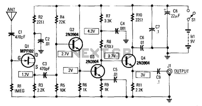
This circuit provides a gain of 14 to 20 dB at frequencies ranging from 10 kHz to 30 MHz. The antenna length can vary between 5 and 10 feet, with a 102-inch CB whip being particularly suitable for this...
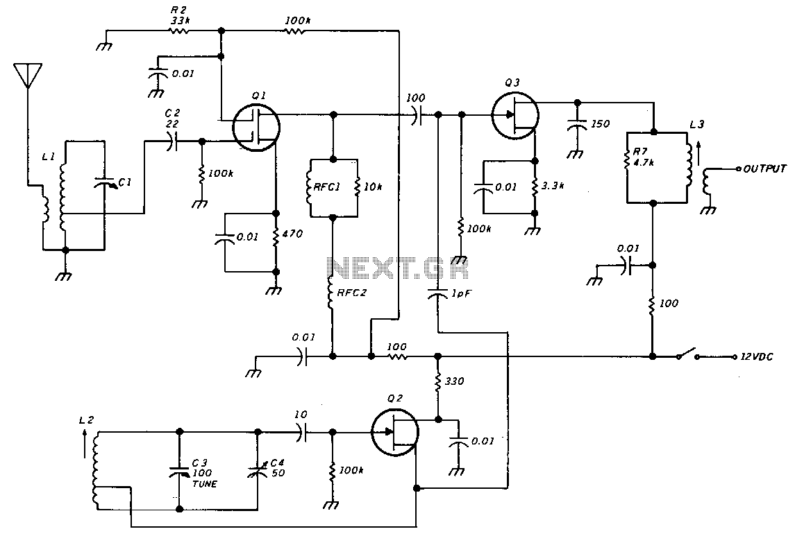
The unit consists of an RF amplifier Q1, a local oscillator Q2, and a mixer Q3. The two frequency bands are covered without a band switch by utilizing an intermediate frequency (IF) of 3.5 MHz. The oscillator operates within...
The schematic is very simple and includes, in addition to Nutchip, with its three driving transistor and LED, the radio receiver. The data come from the OUT pin of the receiver and enter the pin REMOTE remote control. The...
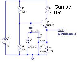
An oscillator circuit capable of generating a high-quality sine wave with a frequency of at least 500 MHz, intended for RFID applications. There have been attempts to utilize a class E oscillator, but the design has not yet been...
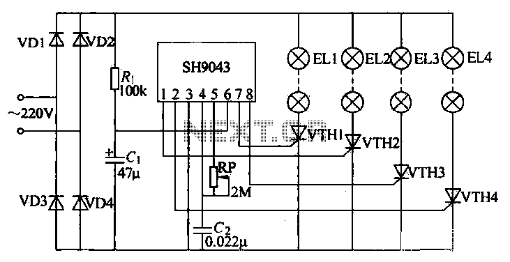
This example demonstrates a robust design featuring novelty lights that flash in a specific sequence, utilizing a 1-3-2-4 vault chase mode. The circuit includes diodes VD1 to VD4, which form a bridge rectifier, converting AC voltage to a full-wave...
Programming of the PIC microcontroller is required prior to its utilization in this circuit, which necessitates the use of a programmer. A suitable programmer can be located by searching for "Multi-PIC Programmer." The PIC microcontroller serves as the core component...
Warning: include(partials/cookie-banner.php): Failed to open stream: Permission denied in /var/www/html/nextgr/view-circuit.php on line 713
Warning: include(): Failed opening 'partials/cookie-banner.php' for inclusion (include_path='.:/usr/share/php') in /var/www/html/nextgr/view-circuit.php on line 713