
A simple TTL modulated diode laser
The circuit design for measuring distances using a modulated laser incorporates several essential components to ensure reliable operation and user control. The 7805 voltage regulator is responsible for providing a stable +5 V power supply, which is crucial for the proper functioning of the entire circuit. This fixed voltage is followed by the LM317 adjustable voltage regulator, which is set to output a precise 3 V for the laser diode module. This careful voltage regulation is vital, as the laser module is sensitive to overvoltage conditions that could lead to immediate failure.
The 7407 non-inverting open collector driver IC plays a critical role in modulating the laser beam. It allows for easy control of the laser module through a TTL signal, enabling precise on/off modulation as required for distance measurement applications. The inclusion of a protective diode at the input stage is a thoughtful design choice, safeguarding the 7407 driver IC from potential over-voltage conditions that could arise from external inputs.
The physical assembly of the circuit reflects careful consideration of insulation and safety. The laser diode module, which is mounted within a metal enclosure, requires proper insulation to prevent short circuits between its frame, which is at a +3 V potential, and the metal enclosure grounded at 0 V. Epoxy glue is used for secure attachment, ensuring that the module remains stable during operation.
On the circuit board, the layout is optimized for accessibility and functionality. The 7805 regulator is positioned on the far right, while the LM317 is adjacent to a ten-turn potentiometer, allowing for fine adjustments to the output voltage. The 7407 driver is conveniently located on the far left, facilitating easy connections. The rear of the device features a four-pole connector for power input and a BNC connector for the TTL input, making it user-friendly for various applications.
LED indicators enhance the usability of the device, with a green LED signaling when power is supplied and a red LED indicating when the laser beam is actively emitting. The operation of the laser can be controlled through a switch or by applying a low-level TTL signal to the BNC jack, providing flexibility in how the device is used in different scenarios. This comprehensive design ensures that the circuit is not only functional but also user-friendly, making it suitable for a range of distance measurement tasks.Measuring distances using a modulated laser. The circuit I created (see above) is very simple and does not need many explanations. The first part consists of a fixed voltage regulator 7805 to derive a stable +5 V source. This is followed by a LM317 adjustable voltage regulator since the diode laser module I found in my spare parts requires exactly 3 V - everything above this will kill the module immediately. Since I want to be able to modulate the laser beam by a TTL input signal, the circuit contains a 7607 non-inverting open collector driver IC which controls the laser module. The TTL input stage has a simple diode to protect the 7407 if a positive input voltage larger than +5 V is applied to the input jack.
The picture on the right shows the front plate of the completed device. In the middle the laser diode module is visible which I glued into the metal enclosure by epoxyd glue. This was necessary since the frame of the diode module is at +3 V potential while the outer metal enclosure is at ground potential, so it is necessary to insulate the diode module from the frame.
On the left the laser diode module can be seen which was originally part of a cheap laser pointer. The blue wire is ground while the yellow wire is +3 V. To the right of the module the 7407 driver can be seen. The picture on the right shows the component side of the circuit board I built. On the far right the 7805 voltage regulator can be seen while the LM317 is located left to the yellow ten turn potentiometer which is used to adjust the +3 V supply. The driver circuit 7407 is on the far left. The rear side of the completed device can be seen in the picture on the right. The four pole connector on the lower left side is the power connector - the BNC connector on the upper left is the TTL input for the modulator circuit.
The green LED will be lit when power is on (this is controlled by the switch on the lower right) while the red LED will be lit when the laser beam is on. Switching the laser beam on is performed by either toggling the switch on the upper right or by applying a low level TTL signal to the BNC jack.
🔗 External reference
Related Circuits
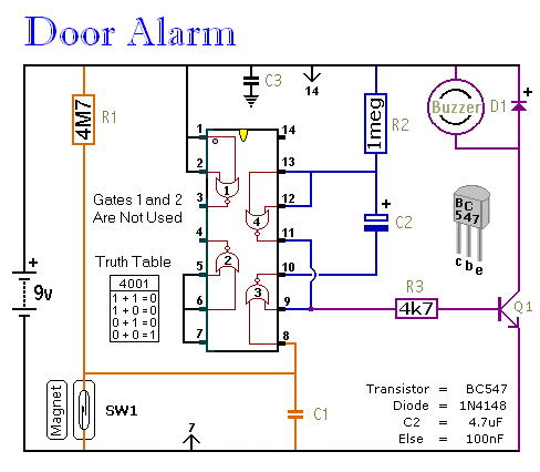
This is a straightforward and easy-to-assemble multi-purpose alarm system. It can be constructed using stripboard or veroboard along with a few inexpensive, readily available components. The alarm is designed to be installed on doors, windows, sheds, garages, cupboards, and...
This Alarm can be used to protect your property, Inside or Outside. And it can protect a Very Large area such as the complete perimeter of your yard. Be Aware: There are some Possible Drawbacks: Snow or Fog could...
Introduction The design of off-line constant voltage, constant current (CVCC) power supplies using the NCP1014 for devices such as cell phones, hand tools, and similar battery chargers can present various challenges when low cost and circuit simplicity are required...
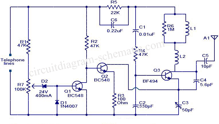
This circuit diagram represents a simple yet effective transmitter circuit, capable of transmitting telephone conversations. When the telephone receiver is on the hook, the line voltage is approximately 48 volts. The R7 preset resistor is adjusted to achieve a...
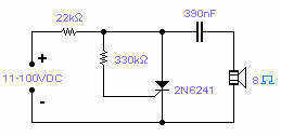
Silicon controlled rectifiers (SCR) can easily oscillate if there is an inductor (a speaker coil in this case) which gives just enough extra voltage to completely switch off the sustain current. In this way a new cycle may start...
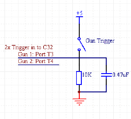
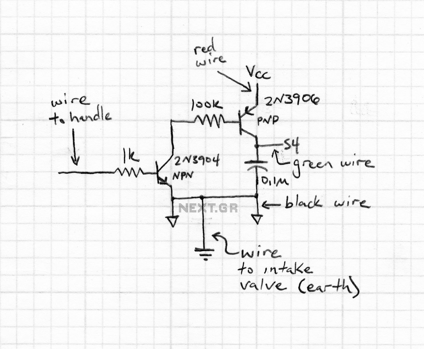
To create two laser guns for a game, red lasers were mounted in modifiable toy guns that players could hold and shoot with. Small red lasers were sourced from Fry's, which the target photocells can reliably detect as a...
Warning: include(partials/cookie-banner.php): Failed to open stream: Permission denied in /var/www/html/nextgr/view-circuit.php on line 713
Warning: include(): Failed opening 'partials/cookie-banner.php' for inclusion (include_path='.:/usr/share/php') in /var/www/html/nextgr/view-circuit.php on line 713