
Laser Beam Alarm

The described alarm system employs modified laser pointers as the primary light source to create a perimeter security system capable of monitoring large areas, such as the boundaries of a yard. The system operates on the principle of laser beam interruption, where a laser beam is emitted and, if interrupted by an object, such as an intruder, triggers an alarm.
The circuit design includes the following key components:
1. **Laser Pointer**: A low-cost laser pointer serves as the light source. It is modified to ensure continuous operation rather than being activated by a button. This may involve bypassing the internal switch and connecting the laser directly to a power source.
2. **Photoresistor (LDR)**: Positioned at the receiving end, the light-dependent resistor detects the laser beam. When the beam is uninterrupted, the resistance remains low, allowing current to flow freely. If the beam is obstructed, the resistance increases, which can be detected by the circuit.
3. **Microcontroller or Comparator Circuit**: The change in resistance from the LDR can be fed into a microcontroller or a comparator circuit that continuously monitors the voltage level. When the voltage drops below a certain threshold (indicating that the laser beam has been interrupted), the circuit triggers an alarm.
4. **Alarm System**: The alarm can be a simple buzzer or a more complex alert system that may include an LED indicator. The alarm circuit is activated when the microcontroller or comparator detects a beam interruption.
5. **Power Supply**: A suitable power source, such as batteries or a DC power adapter, is necessary to power the laser pointer and the alarm circuit. Consideration should be given to power management to ensure long operational life.
6. **Environmental Considerations**: The design accounts for potential environmental interferences, such as snow or fog, which can obstruct the laser beam and cause false alarms. Possible solutions include using a more narrow beam laser, positioning the laser at an angle to minimize the chances of obstructions, or implementing a dual-beam system to enhance detection reliability.
7. **Multiple Units**: For larger properties or complex layouts, it is advisable to deploy multiple alarm units. Each unit can be configured to monitor different sections of the property, creating a comprehensive security system that allows for refined detection capabilities.
This alarm system is suitable for both indoor and outdoor applications, providing a flexible and scalable solution for property protection. However, careful consideration of installation locations and environmental factors is essential to minimize false alarms and maximize effectiveness.This Alarm can be used to protect your property, Inside or Outside. And it can protect a Very Large area such as the complete perimeter of your yard. Be Aware: There are some Possible Drawbacks: Snow or Fog could Block the Beam, Giving a False Alarm. You may also want to Build More than one of these alarms, so as to detect intruders in Different area`s, Making a More Refined System. It uses the Cheap "Laser Pointers" (Slightly Modified) as the laser light source and they are found
🔗 External reference
Related Circuits
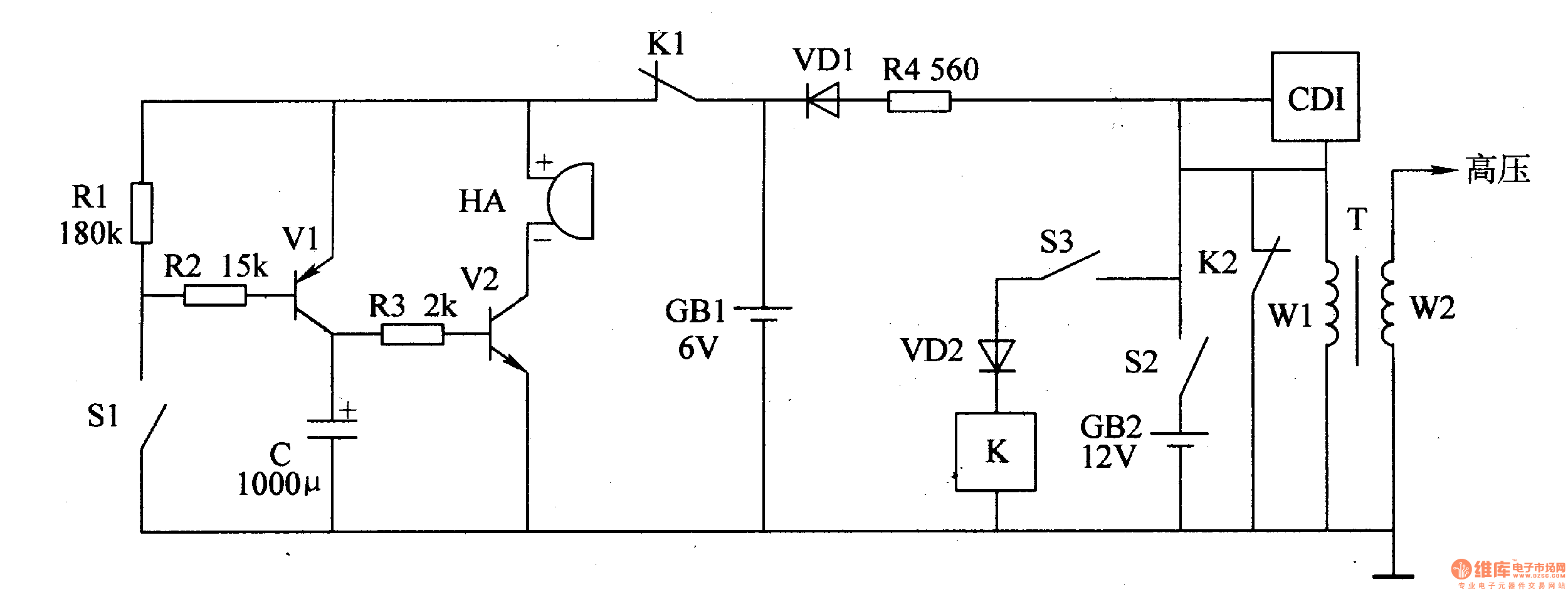
The motorcycle anti-theft alarm circuit consists of a detection alarm circuit, a charging circuit, and an anti-theft control circuit, as illustrated in figure 7-94. The detection alarm circuit includes a mercury switch (S1), resistors (R1-R3), a capacitor (C), transistors...

As the resistance (Rl) increases with a decrease in temperature, the output of integrated circuit IC1 becomes positive, activating transistor Q1. When Q1 conducts, it also triggers transistor Q2, which in turn activates the audible alarm. The threshold level...
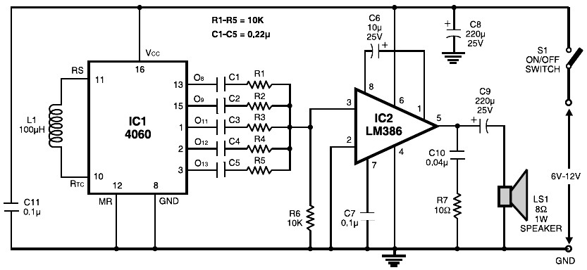
The circuit is built around the popular CMOS oscillator-divider IC 4060 and a small audio amplifier LM386. The IC 4060 functions as a multitone generator. A 100 H inductor is used at the input of the IC 4060, allowing...

Motorcycle Alarm Number 4. This is a simple, easy-to-build, transistor-based motorcycle alarm. It is designed to operate at 12 volts; however, it can be adapted by changing the relay to a different specification. This motorcycle alarm circuit utilizes a transistor...

The core of this overheat detector circuit features a precision integrated temperature sensor, the LM35 (IC1). This sensor provides a linear and directly proportional output in millivolts over a temperature range of 0 to +155 degrees Celsius. The LM35...
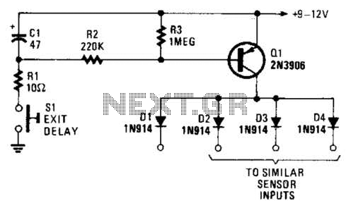
Depressing SI charges CI to the supply voltage. This biases Q1 on via bias resistors R2 and R3. A voltage is available for the duration of the delay period to hold off the alarm circuit. CI can be increased...