
Simple Telephone Transmiter

This transmitter circuit operates based on the principle of detecting the state of a telephone receiver. The line voltage is crucial for determining the operational state of the circuit. When the receiver is on the hook, the high line voltage allows for the Zener diode D2 to function in its breakdown region, which is essential for the activation of transistor T1. The conduction of T1 is significant because it controls the state of T2, effectively isolating the transmitter from the line to prevent unwanted signal transmission during idle periods.
The R7 preset resistor plays a vital role in fine-tuning the voltage at the cathode of D2, ensuring that the Zener diode operates correctly at its breakdown voltage. The precise adjustment of this resistor is essential for maintaining the desired functionality of the circuit.
Upon lifting the receiver off the hook, the line voltage drops to approximately 11 volts, which alters the operational state of the transistors. This voltage drop ceases the conduction of T1, thereby allowing T2 to turn ON. The activation of T2 enables the circuit to transmit audio signals, facilitating the transmission of telephone conversations.
This circuit design emphasizes the importance of voltage levels in controlling the state of transistors, which are pivotal in switching applications. The simplicity of the design, combined with the effective use of Zener diodes and transistors, makes it a practical solution for audio transmission in telecommunication systems. Proper understanding and implementation of this circuit can lead to successful applications in various telecommunication projects.This circuit is a circuit diagram of a simple transmitter, but very useful circuit which can be used to transmit telephone conversations. When the telephone receiver on the hook to the line voltage of about 48 volts. R7 preset is adjusted to 24.7 V between the cathode of D2 and ground. In voltage Zener diode D2 will be in the breakdown and the transistor T1 will conduct. This makes the transistor T2 OFF. When the receiver off the hook, the line voltage drops to about 11 volts. This makes the tra. 🔗 External reference
Related Circuits
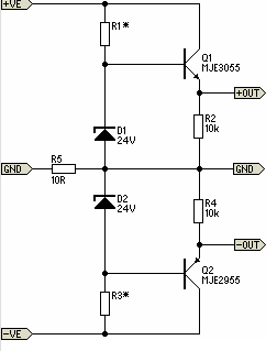
There will be many occasions when it is beneficial to utilize the P05 supply module sourced from a higher voltage supply. For instance, this could be advantageous when integrating balanced inputs. The P05 supply module is designed to facilitate the...

A simple yet reliable car battery tester circuit diagram. This circuit utilizes the popular and easily accessible LM3914 integrated circuit (IC). The LM3914 is straightforward to operate, does not require external voltage regulators due to its built-in voltage regulator,...
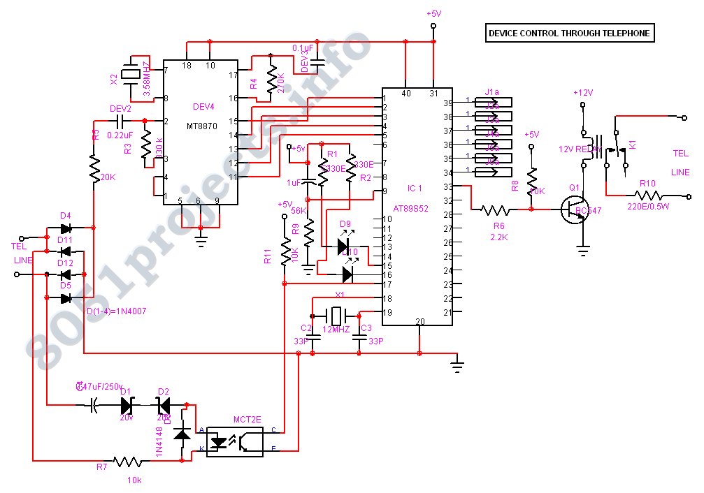
This Project is used to control our household electrical devices from anywhere through the cell phone. The circuit consists of a DTMF tone detector and a powerful 8-bit Microcontroller AT89S52. The microcontroller controls all the system. In this project,...
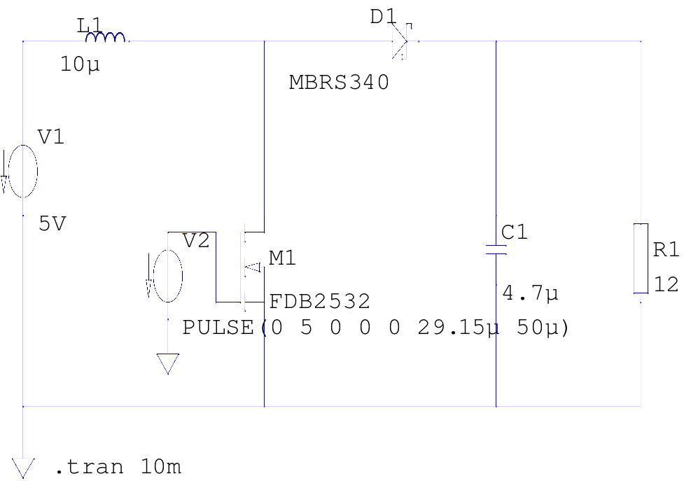
The supply voltage is 5V, and the goal is to increase it to 12V with a load current of 1A, resulting in an output power of 12W. A switching frequency of 20kHz has been selected, requiring a duty cycle...
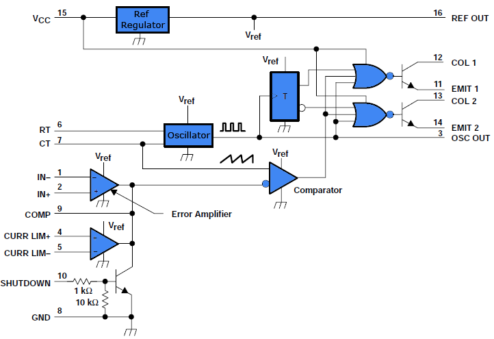
This document outlines a simple PWM (Pulse Width Modulation) DC to AC voltage inverter circuit based on the SG3524 integrated circuit. The SG3524 is a fixed frequency PWM voltage regulator control circuit that offers indifferent outputs suitable for both...
This is the basic interface I used as part of my Computerized Room project. This is the parallel interface only. The 8 bit input card can be found, along with the rest of the project, at Computerize Your Room/House....