
A stator coil connection

The stator coil is a critical component in electric machines, particularly in alternating current (AC) motors and generators. The two primary configurations for connecting the stator windings are the triangular (delta) and star (wye) connections.
In the triangular connection, each coil is connected end-to-end, forming a closed loop. This configuration allows for higher phase currents and is typically used in applications where high starting torque is required. The delta connection can also provide a more robust performance under varying load conditions, as it allows for better distribution of current across the coils.
Conversely, the star connection involves connecting one end of each coil to a common point, while the other ends are connected to the supply voltage. This configuration results in lower phase currents and is generally used in applications where high starting torque is not as critical. The star connection can also simplify the design of the control circuits and reduce the overall voltage across each coil, which can be beneficial in certain operating conditions.
In both configurations, the choice between triangular and star connections significantly impacts the performance characteristics of the motor or generator, including efficiency, torque, and operational stability. Understanding these connections is essential for engineers designing electrical systems to ensure optimal performance and reliability.A stator coil connection Shows the structure and connections of the stator coil, and FIG. (A) shows a triangular connection, Figure (b) shows a star connection, star connection in two forms.
Related Circuits
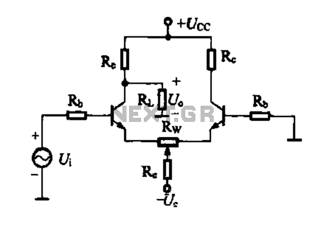
A differential amplifier circuit can be connected in four different ways, allowing for a comparison of their characteristics. The gain of the amplifier is equivalent to that of a single tube, with half the gain providing a high common-mode...
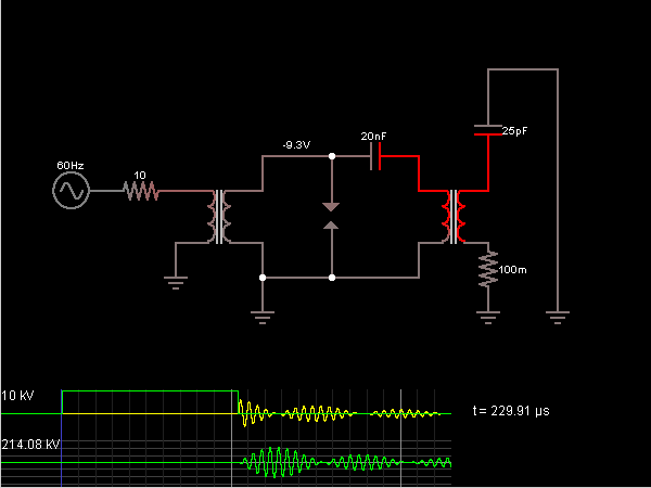
This is the Tesla Coil circuit diagram with a detailed explanation of its working principles. The electronic circuit simulator aids in designing the Tesla Coil circuit and simulating it online for better understanding. The Tesla Coil is a resonant transformer...
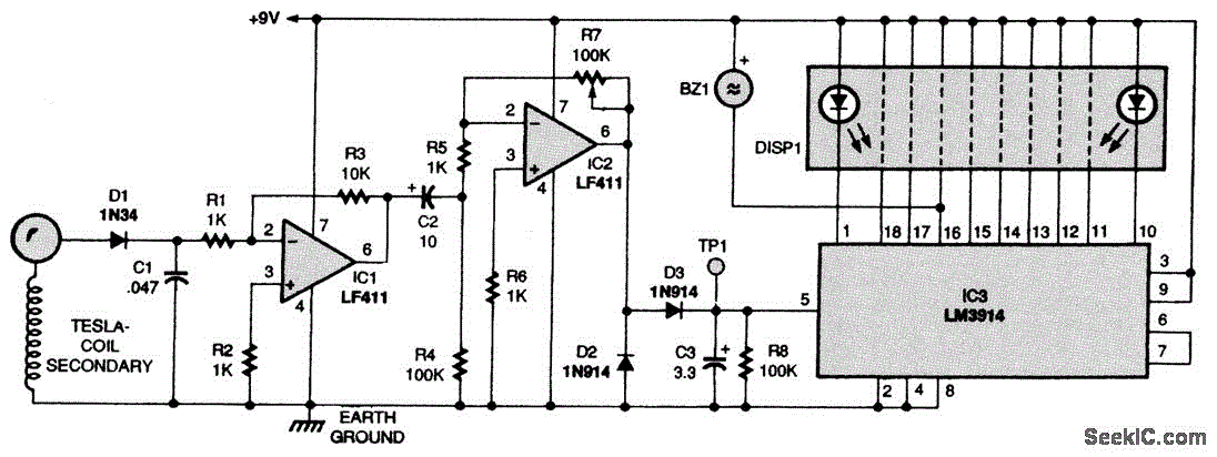
Here is a Tesla coil secondary design: Wind 750 turns of 24-gauge enameled magnet wire onto an 18-inch long piece of 1.9-inch outer-diameter PVC pipe. The large coil has an inductance of approximately 2800 mH and a self-capacitance of...
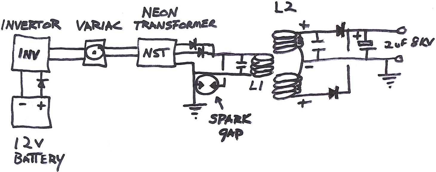
This diagram illustrates all components necessary to create a self-sustaining power supply. The input is a 12V DC, 7Ah lead-acid or gel cell battery (not depicted). This input connects to a 12V DC to 120V AC inverter rated approximately...
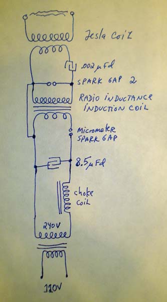
Many individuals assume that spark gap Tesla coils require high voltages, typically ranging from 4 kV to 15 kV or more. However, some interesting experiments can be conducted using as little as 240 V directly. Aside from very low...
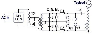
Instructions for constructing a 1kW synchronous rotary spark gap (SRSG) Tesla Coil. This device operates using mains power and is powered by a 1kVA (10mA, 10kV) neon sign transformer (NST). The construction of a 1kW synchronous rotary spark gap Tesla...