
Tesla Coils

Before the coils, an enclosed spark gap is connected to the neon transformer ground and one end of the L-1 coil and the capacitors. The junction of the wire and the spark gap serves as the grounding lug for this section of the system. The capacitors are positioned in parallel across the two wires of the L-1 coil (red), with high-voltage diodes connected from different points converging at the capacitors. It is crucial to observe the polarity of these diodes, which should be rated for at least twice the transformer's output.
The L-1 coil receives the generated power and determines the voltage step-up ratio. For instance, with 2500 volts from the transformer and 10 turns on the L-1 coil, each turn transfers 250 volts to the L-2 winding. Therefore, if the L-2 coil has 30 turns, the output voltage becomes 7500 volts, with further increases possible by adding more turns. The L-1 coil consists of 5 turns wound on a 2-inch PVC tube, with multi-stranded connecting wires running through the tube. This adjustable coil configuration allows for tuning according to Nikola Tesla's designs from around 1896.
The L-2 coil is a Barker-Williamson design, measuring 10" x 3" with 40 turns of tinned copper wire (10 or 12 AWG), featuring 4 turns removed in the middle for connections. This coil is wound at a density of 4 turns per inch and incurs a cost of approximately $100, although it can be constructed at a lower expense by wrapping the wire around a form. The L-2 coil is split in the middle and connected at the grounding lug to enhance control over frequency and current.
At this stage, safety precautions are paramount, as the system can produce lethal voltages. High-voltage safety protocols must be strictly adhered to, as Tesla's designs were capable of generating significant power beyond mere electrical discharges.
The L-2 coil connects at three points: the top positive terminal, the middle negative terminal, and the bottom positive terminal. A 0.047uF high-voltage capacitor is placed across the top positive and middle negative terminals, as only one is needed due to the series configuration of the L-2 coil. High-voltage diodes rectify both the upper and lower positive outputs, resulting in pulsed DC. The capacitor bank, consisting of four 2000V DC, 8uF oil-filled capacitors arranged in series (not parallel), provides a continuous output of 8000 volts at 20 amperes. This configuration is crucial for harnessing power efficiently from the system.In this picture is everything you will need to make a self running power supply. The input is a 12vdc 7ah lead acid or gel cell battery (not shown). The input goes to a 12vdc to 120vac inverter of about 200 watts more or less, it is not critical as long as it can turn on the next part, the transformer. The transformer is a 9000v, 30ma, 35khz neon sign transformer with two outputs that are rectified and its output is controlled by the variac for neon signs after the inverter. The next thing you see is two high voltage capacitors of. 1uF 4000vdc. They are in parallel which makes. 2uF 4000vdc. These are the self healing type, though not critical as long as you keep the transformer adjusted to 4000 volts or less.
Don keeps it down around 2000 to 3000 volts. The next part before the coils is the enclosed spark gap connected to the neon transformer ground and the one end of the L-1 coil and the capacitors. Where the wire and the gap meet is also your grounding lug for this part of the system. If you look carefully at the capacitors, you will see that they are in parallel across the two L-1 coil wires (red) and the high voltage diodes are coming from two different connections and meeting at the capacitors.
Look carefully at the polarity of the diodes. These diodes should be rated at least 2 times the output of the transformer. The next part is the L-1 coil that takes the power that you have generated and sets how much you are going to step it up. For example: If you have 2500 volts coming from the transformer and you have 10 turns on your L-1 coil, then you divide 2500 by 10 and you get 250 volts to transfer to each L-2 winding.
So if you have 30 windings on your L-2 coil, then you will have stepped the voltage up to 7500 volts. 60 windings = 15000 volts. 100 windings = 25000 volts and so on. Get it So far its basic Tesla stuff. In this setup, the L-1 coil (the one going through the middle of the bigger coil) has 5 turns on a 2" PVC tube with the connecting wires running through the inside of the tube.
The wires for the L-1 coil are multi-stranded. This is an adjustable coil setup for tuning the coils as per Nikola Tesla`s design circa 1896. The L-2 coil is a Barker-Williamson 10" x 3" 40 turn tinned copper coil 10 or 12 Awg with 4 turns removed in the middle (or unwound for connections). This coil is 4 turns per inch and costs about $100. 00. You can make your own by wrapping your wire around a form for a lot less! If you will notice, the L-2 coil is separated in the middle and then hooked together at the grounding lug in the middle.
This is for better control of the frequency and amperage. that`s right, I said AMPERAGE! At this stage of the game, this mother will kill you instantly so be careful! High voltage rules apply here! Tesla definitely knew how to produce more than just sparks! In the following Tesla diagrams, the top one is how to finish the circuit for high frequency power and the bottom left is the coils in the device in this article. Notice in the bottom left the L-1 coil inside the L-2 coil with the split coils and the center tap for amperage Look like anything we are building here If Tesla coil builders would just look and read what Tesla was really after and accomplished, they would have a lot more than just sparks flying from their coils!
They would have real usable power in the kilowatt to megawattrange! Ok, on with the picture. At this point the L-2 coil is connected in 3 places. The top +, the middle -, the bottom +. Across the top + and the middle - is a. 047 uF high voltage capacitor. You only need the one because of the L-2 coil being hooked in series. The high voltage diodes are rectifying both top and bottom positives giving you pulsed DC. The capacitor bank (the gray ones on the right) are four 2000vdc 8uF oil filled caps in series NOT parallel, giving this setup a continuous 8000 volts @ 20 amperes of power. The trick to using this power from 🔗 External reference
Related Circuits

The component in question is complex, seemingly consisting of three capacitors: two virtual capacitors and one physical capacitor. Initial observations indicate that the voltage is increasing, and the LED brightness is also improving. Battery B1 appears to be discharging...
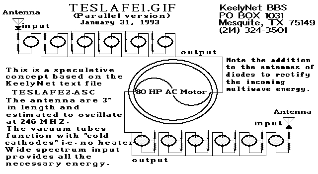
Two schematic diagrams illustrate a series and a parallel circuit configuration that Tesla may have utilized. The components featured are the 70L7GT Half Wave Rectifier tubes, which are surprisingly still available today. While there is an interest in accessing...
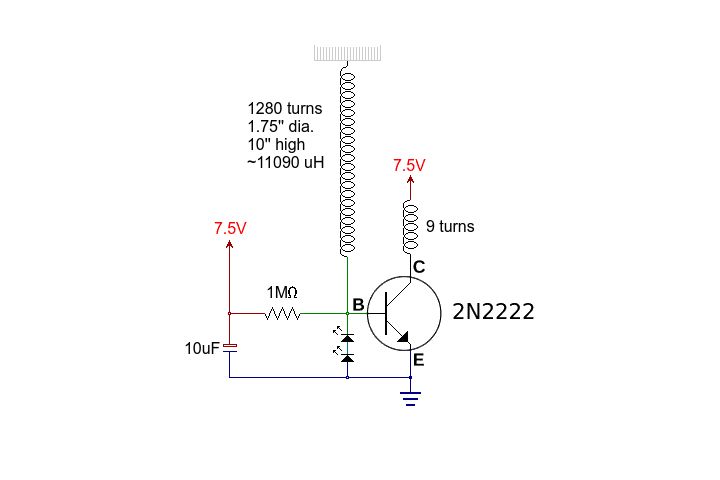
This circuit is straightforward. The accompanying graphics and images provide all necessary details. After gathering all materials, connect the transistor according to the provided schematic. The circuit in question is a basic transistor circuit that serves as an introductory project...
A South African company has developed a 5-kilowatt Fuel Free Generator and discovered that the longevity of the batteries is significantly affected by the process. There are various types of batteries available for testing, including different lead-acid batteries, gel...
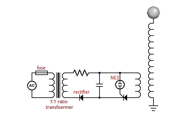
Power is supplied to transformer T1, a small neon-sign transformer, which steps up the voltage to approximately 3000 Vac. The stepped-up output from T1 is routed through inductors L1 and L2 and across capacitor C1, allowing the capacitor to...
An SCR (Silicon Controlled Rectifier) functions similarly to a diode, allowing current to flow in one direction and can be turned on; it remains in this state until the power is interrupted. The query arises regarding its application in...