
F232 is USB powered
The F232 is a USB interface device that facilitates communication with RS232 systems. To ensure proper signal levels between the F232 and the RS232 interface, a level translator is essential. The F232 outputs a digital signal compatible with USB standards, which typically operates at lower voltage levels than those required by RS232. The MAX232 is a commonly used integrated circuit that converts TTL (Transistor-Transistor Logic) levels to RS232 voltage levels, allowing for effective communication between the two systems.
In this configuration, the Tx pin of the F232 is connected to the input of the MAX232, which then translates the signal to the appropriate RS232 levels. The design also incorporates a power supply arrangement that ensures the MAX232 receives sufficient voltage to operate correctly. This is particularly crucial because the RS232 standard requires higher voltage levels for signal integrity over longer distances.
For the receive (Rx) side, the use of an opto-isolator can provide electrical isolation between the F232 and the RS232 device, protecting both devices from potential voltage spikes or ground loop issues. The opto-isolator converts the RS232 signal back to TTL levels that the F232 can interpret.
The modification to replace the original RS232 chip with the MAX232 enhances the reliability and performance of the circuit. The MAX232 is favored for its ability to operate with a low supply voltage while still conforming to RS232 standards. The circuit layout, while not based on FTDI’s provided Gerber files, maintains compliance with necessary electrical specifications, ensuring that the custom design functions effectively within the intended application.
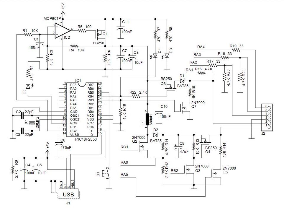
Overall, the integration of the F232 with the MAX232 level translator creates a robust solution for interfacing USB devices with RS232 systems, facilitating seamless communication and data transfer between disparate technologies.F232 is USB powered, but you need to have a level translator at the output of F232. Tx of f232 has to be converted to RS232 levels, since the other side has a max. Receive pin can be easily opto-ed. But the transmit pin, need to have a supply in line with RS232 levels. Sometimes we d it by making a higher supply from the remote RS232 chip - a comm on method, if you are in control of the remote max pin. Here is the circuit. I modified the circuit to replace rs232 chip with MAX232 to the board sold by FTDI guys. FTDI has got circuit + gerbers in their site. I did not use their gerbers. Got a layout made by someone. 🔗 External reference
Related Circuits
Life in the 21st century would be almost unbearable without some of the computer peripherals that PC users now look upon as essentials, such as keyboards, mice, and printers. Computer peripherals play a crucial role in enhancing the functionality and...

The CMOS 4001 consists of four independent two-input NOR gates. These gates are organized into two pairs. Gates 1 and 2 are connected to form a latching circuit. When the alarm is triggered, they will latch and activate the...
The modification made is based on the SC1 modification by Steve Chambers and further improvements by Phil Davis, but it does not utilize the additional parallel port connection. All differences from the original SC1 modification and Phil's improvement are...
PICkit 2 Introduction: There are many PIC programmers available, including commercial and DIY devices. As Microchip introduces new microprocessors, the programming tools must also evolve to support these advancements. The PICkit 2 is a versatile development tool designed for programming...

When powering a computer, various peripherals (such as printers, screens, scanners, etc.) often need to be turned on and off simultaneously. Utilizing the 5-V supply voltage from the USB interface on the PC allows for easy control of these...
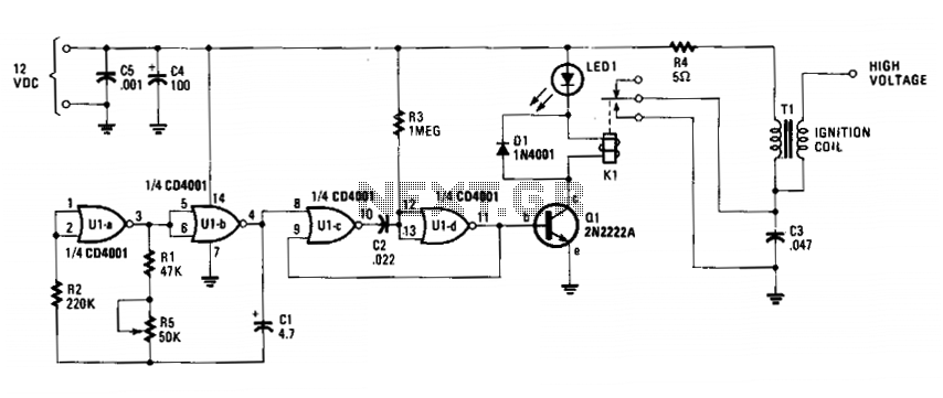
The circuit is fundamentally an auto ignition coil paired with a set of points that perform a similar function. It employs a pulsing circuit constructed from a single CMOS NOR integrated circuit (U1) to open and close relay contacts,...