
Automatic Inverter Supply and Mains Supply Changeover Relay
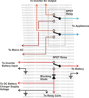
The proposed circuit employs a relay-based mechanism to facilitate automatic switching between the inverter and the mains power supply. The heart of this system consists of a double-pole double-throw (DPDT) relay configured to toggle the connection based on the availability of AC mains power. When mains power is present, the relay is energized, directing the output to the mains supply while simultaneously connecting the battery charger to the inverter battery to ensure it remains charged. In the event of a power failure, the relay de-energizes, instantly redirecting the output to the inverter, which then supplies power from the battery to the connected load.
To implement this system, the relay should be rated appropriately for the load it will control, ensuring it can handle the maximum current and voltage requirements. Additionally, a suitable power supply is needed to energize the relay coil, which can be derived from the mains voltage or an auxiliary power source. It is also essential to include protection elements, such as diodes across the relay coil, to prevent back EMF from damaging the circuit components when the relay is switched off.
For added reliability, a delay circuit may be integrated to prevent rapid switching during transient conditions, such as momentary power fluctuations. This delay can be implemented using an RC timing circuit or a microcontroller, which would monitor the AC mains status and control the relay accordingly.
Overall, this relay assembly module provides a robust solution for automatic power switching, ensuring uninterrupted operation of connected appliances during mains power fluctuations. The design emphasizes simplicity and efficiency, allowing for seamless transitions between power sources without user intervention.I have been put forth with this question many times in this blog, how do we add a change over selector switch for automatic toggling of an inverter when AC mains is present and vice versa and also the system must enable automatic switching of the battery charger such that when AC mains is present the inverter battery gets charged and when AC mains fails, the battery gets connected with the inverter for supplying AC to the load. The configuration should be such that everything takes place automatically and the appliances are never switched OFF, just reverted from inverter AC to Mains AC and vice versa during mains powerfailuresand restorations. So here I am with a simple yet very efficient little relay assembly module which will do all the above functions without letting you know about the implementations, everything is done automatically, silently and with great fluency.
The shown position of the relays are in the N/C directions, meaning the relays are not powered, which will obviously be in the absence of the mains AC input. The connected appliances are instantly diverted from the inverter AC to the mains AC within a split second such that the appliances doesnt even blink, giving an impression that nothing had happened and the are kept operative continuously without any interruptions.
🔗 External reference
Related Circuits
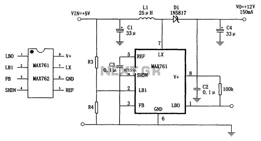
The circuit depicted in the figure illustrates an efficient, low-power step-up DC-DC converter, the MAX761, along with a few external components, which functions as a +5V to +12V boost power supply. Its characteristics include a conversion efficiency of 86%...
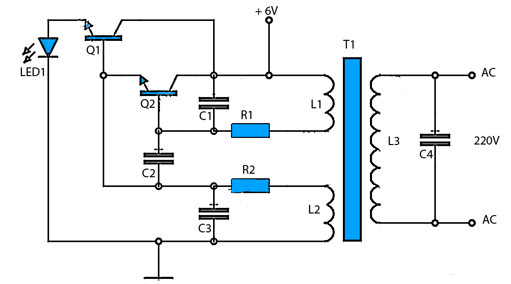
The circuit schematic presented is a voltage inverter circuit that converts a 6-volt DC input into a 220-volt AC output. It is designed to deliver a maximum output power of 30 watts and operates with a low input current....
The micropower circuit automatically provides shutdown, power-up, and low-battery lockout functions without requiring software or operator control. The micropower circuit is designed to manage power efficiently in battery-operated devices, ensuring optimal functionality while conserving energy. The shutdown feature is activated...
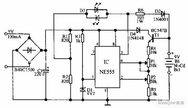
An automatic Ni-Cd battery charger circuit is depicted in the provided image. The internal comparator of the NE555 timer is configured to a reference voltage of 4.7V using a Zener diode. When the voltage at pin 6 exceeds this...
A power supply project that operates without a traditional transformer, potentially saving costs but also presenting lethal voltages at the output terminals. This project should not be attempted by beginners due to the electric shock hazard. In the UK,...
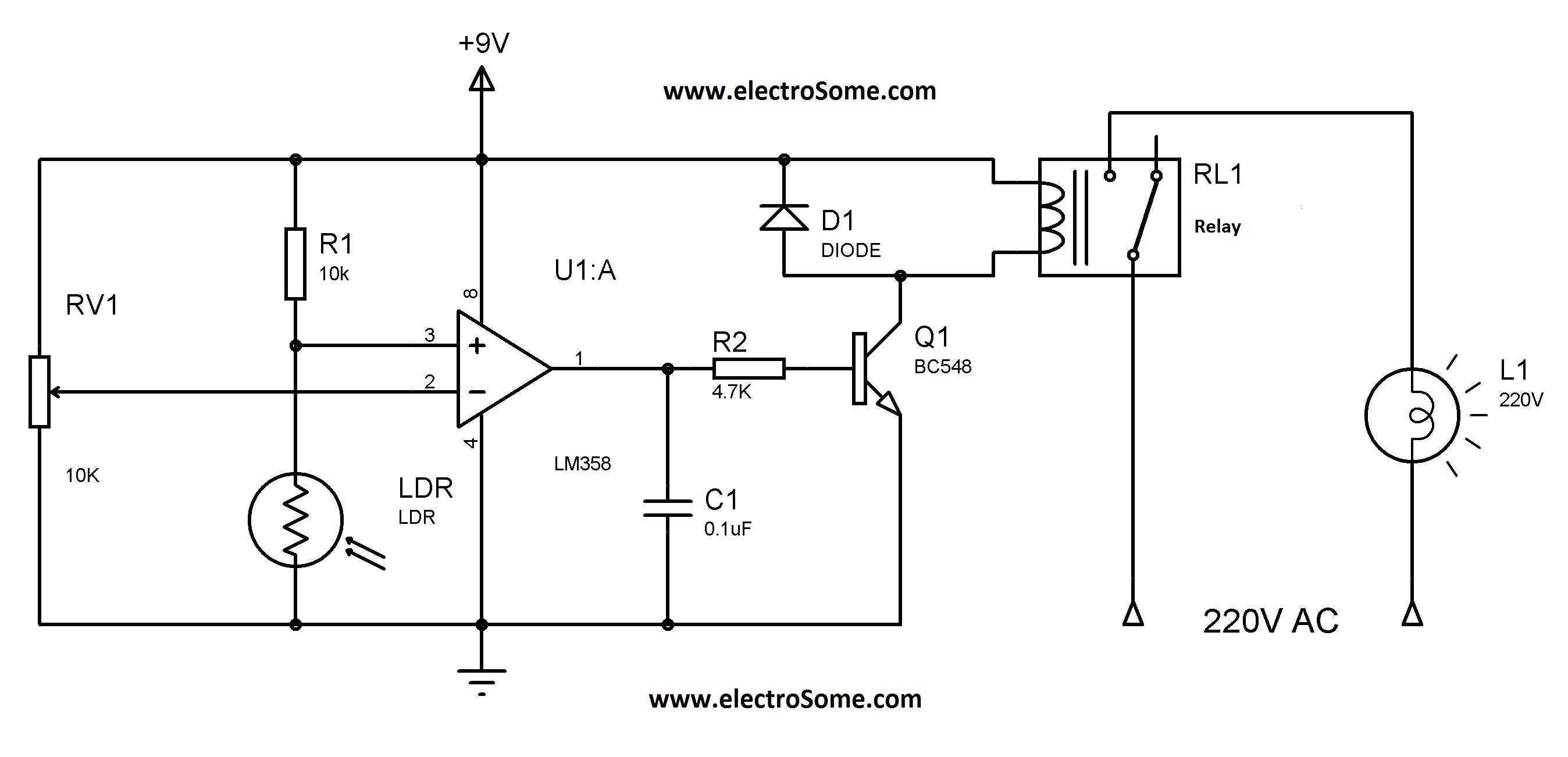
Similar to the previous circuit utilizing the LM358, this design is also cost-effective, priced under 100 rupees. It is a circuit intended for the automatic control of street lights and garden lights. Users do not need to manually turn...