
A Unipolar Stepper Motor Driver
```cpp
int PIN_CLK = 10;
void setup() {
pinMode(PIN_CLK, OUTPUT);
digitalWrite(PIN_CLK, LOW);
}
void loop() {
digitalWrite(PIN_CLK, HIGH);
delay(2);
digitalWrite(PIN_CLK, LOW);
delay(2);
}
```
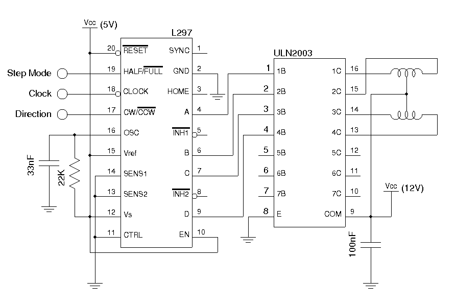
The circuit for driving unipolar stepper motors is designed to achieve simplicity while still allowing for effective control of motor functions. The use of transistors or MOSFETs as switches for each winding ensures that the current through the coils can be controlled with minimal components. The L297 IC serves as the core of the control system, generating necessary signals for stepping and direction.
In a typical configuration, the four windings of the unipolar stepper motor are connected to the outputs of the L297. The SENSE pin, when employed, allows for current sensing, enabling the implementation of current limiting features through PWM control. However, in this simplified design, the SENSE and CONTROL pins are grounded, which means that the motor operates without additional complexity, providing sufficient performance for many applications.
The Arduino MCU acts as the control unit, generating a clock signal that dictates the stepping of the motor. The choice of digital pin 10 for output is common, and the program structure allows for easy modifications should the user wish to implement different stepping modes or directions later on. The bit-banging method used in the code provides a straightforward way to control the timing of the pulses sent to the motor, ensuring consistent operation.
The circuit can be easily expanded or modified, allowing for additional features such as microstepping or more complex control algorithms if needed in future applications. The design is versatile and can serve as a foundational platform for various robotics and automation projects involving unipolar stepper motors.The drive circuits for Unipolar stepper motors are usually very simple. In its simplest form, a transistor or MOSFET is used to drive each section of the windings. With this design, the control signal must be supplied programmatically to the four windings of the unipolar stepper motor via an MCU. The programming can become quite complex when the s tepping mode (e. g. half stepping/full stepping), stepping direction and rotation speed all need to be controlled. Basically, the L297 is used to generate the stepping signals needed by the stepper motor. The SENSE, CONTROL, INH and VRef pins can be used in tandem to provide finer PWM current control and faster decay. But in all but the most strict applications, these features are rarely needed. So I omitted these features by tying CONTROL and SENSE pins to the ground and set VRef to Vcc. The INH pins are left unused. This way the complexity of the circuit is greatly reduced. If you intend to use these pins, please refer to the following application note (AN470). To test this circuit, I used an Arduino MCU board and used digital pin 10 to generate the required clock signal.
For simplicity, the step mode pin and the direction pin are grounded (full step, counter clockwise) as seen in the picture below, but these two pins can also be controlled programmatically. The actual program is very simple, all we needed to do is to provide a clock signal. The following code used the bit-banging method to generate the clock signal at roughly 250 Hz. int PIN_CLK = 10; void setup() { pinMode(PIN_CLK, OUTPUT); digitalWrite(PIN_CLK, LOW); } void loop() { digitalWrite(PIN_CLK, HIGH); delay(2); digitalWrite(PIN_CLK, LOW); delay(2); }
🔗 External reference
Related Circuits
The NE568A (NE568AD, NE568AN, SA568AD, SA568AN) is a monolithic phase-locked loop (PLL) that operates from 1Hz to frequencies exceeding 150MHz. It features an extended supply voltage range and a lower temperature coefficient of the VCO center frequency compared to...
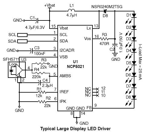
This high-voltage white LED driver electronic circuit schematic utilizes the NCP5021 integrated circuit from On Semiconductor. The NCP5021 is designed with an ambient light sensing feature and can drive up to eight LEDs in series for portable backlight applications....
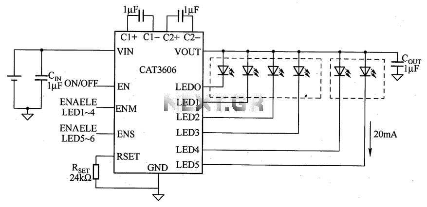
CAT3606 is a high-efficiency white LED driver. This adjustable charge pump is suitable for general-purpose, large-panel, flicker-free white LED backlighting and dual-display systems. The CAT3606 inductor boost circuit can replace conventional high-brightness backlighting requirements, thereby simplifying system design. It...
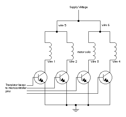
When moving objects with microcontrollers, three types of motors are particularly useful: DC motors, servomotors, and stepper motors. Most motors operate on the electrical principle of induction. When electric current flows through a wire, it generates a magnetic field...
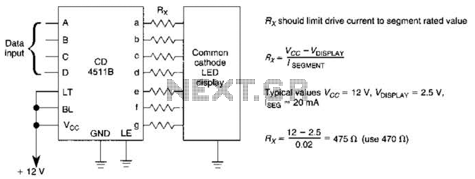
A CD4511B CMOS LED display driver can be utilized to operate a common cathode LED display. Current limiting resistors are employed to restrict the segment current to the specified value at the maximum supply voltage. The CD4511B is a...
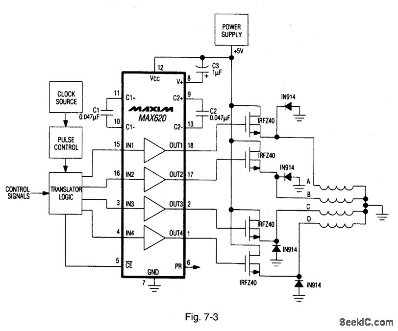
A MAX620 is connected to create a complete stepper motor drive system. TTL/CMOS signals from the logic network are converted to high-side levels that control four N-channel power MOSFETs, which supply current to each of the four phases of...