
Motor circuits
The operation of DC motors is characterized by their simplicity and effectiveness in various applications. These motors consist of a rotor (the rotating part) and a stator (the stationary part), with the rotor typically containing a coil of wire wound around a core. The interaction between the magnetic field generated by the current in the rotor and the external magnetic field from the stator induces rotation. Additionally, the direction of rotation can be reversed by swapping the connections to the terminals, allowing for bidirectional control.
In practical applications, DC motors are widely utilized in robotics, automation, and various electronic devices due to their ease of control and ability to provide precise speed adjustments. The integration of pulse-width modulation (PWM) techniques can further enhance control over the motor's speed and torque, allowing for smooth acceleration and deceleration. It is essential to consider thermal management in motor design, as excessive heat generation can lead to reduced efficiency and potential damage. Proper heat dissipation methods, such as heatsinks or cooling fans, may be necessary to ensure reliable operation over extended periods.
In summary, understanding the principles of motor operation, including current flow, magnetic fields, and torque, is crucial for designing effective electronic control systems. The selection of appropriate motors and power supply considerations, along with protective measures against back voltage, are key factors in the successful implementation of motor-driven applications.When trying to move things with microcontrollers, there are basically three kinds of motors that are most useful: DC motors, servomotors, and stepper motors. Most all motors work on the electrical principle of induction. When you put electric current through a wire, it generates a magnetic field around the wire. By placing a charged coil of wire in an existing magnetic field (say, between two magnets), the coil will be either attracted to one magnet and repelled by the other, or vice versa, depending on the current flow. The higher the current, the greater the magnetic field, and therefore the greater the attraction or repulsion.
The coil is mounted on a spinning shaft in the middle of the motor. As the coil is alternately attracted to one magnet and repulsed by the other, it spins from one to the other, and we get circular motion. All inductive loads (like motors, electromagnets, and solenoids) work on this same principle: induce a magnetic field by putting current through a wire, use it to attract or repulse a magnetic body.
However, the principle works in reverse as well. When you spin a wire in an existing magnetic field, the field induces a current in the wire. So if you`ve got a motor spinning, and you turn it off, the fact that the motor`s coil is spinning in a magnetic field will generate a current in the wire for a brief amount of time. This current comes back in the reverse direction of the current flow you generated to run the motor. It`s called blowback, or back voltage, and it can cause damage to your electronics. Usually it`s stopped by putting a diode in line with your motor, to stop the back voltage. The rated voltage of a motor is the voltage at which it operates at peak efficiency. Most DC motors can be operated somewhat above or below their range, but it`s best to plan to operate them at their rated voltage.
Dropping below rated voltage reduces the motor`s power, and operating above the rated voltage may burn the motor out. Plan on the motor`s top speed being at rated voltage, and slowest speed at no more than 50% less than the rated voltage.
Motors draw current depending on the load they`re pulling. Usually more load means more current. Every motor has a stall current, which is the current it draws when it`s stopped by an opposing force. This stall current is much greater than the running current, or current that it draws under no load. Your power supply for a motor should be able to handle the stall current with extra amperage to spare.
Motors may draw near the stall current for a brief period of time when starting up, to overcome their inertia. Torque is the measure of a motor`s pulling force. It`s measured by the force a motor can pull when the opposing force is attached to a shaft attached to its center rod.
If the shaft sticks out a foot from the motor`s center, and the motor can pull one pound on that shaft, the motor`s torque is one foot-pound. Motor manufacturers haven`t standardized this measurement, so sometimes you will see it as ft. -lb. , lb-ft. , oz. -in, in. -oz. , g-cm (gram-centimeter), and any other weight to length variation you can think of. Often you`ll see a motor rated in ohms. This just gives you the resistance that the motor`s coil offers. Using Ohm`s Law (voltage = current x resistance), you can calculate the motor`s current draw if you know the rated voltage and the coil resistance.
The DC Motor is the simplest of the motors discussed here. It works on exactly the principle discussed above. There are two terminals, and when you apply direct current to one terminal and ground the other, the motor spins in one direction. When y 🔗 External reference
Related Circuits
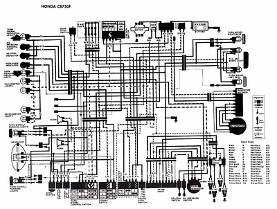
The following image illustrates the electrical wiring connection diagram for the Honda Motorcycle CB750F. It details the connections between various Honda components, including the right turn signal indicator light, oil pressure warning light, neutral indicator, high beam indicator, turn...
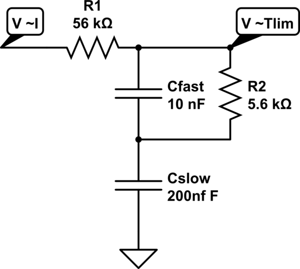
A MOSFET is employed to drive a load that includes a sense resistor in its current path. The voltage across this resistor is utilized to trigger a circuit capable of disconnecting the load in the event of an overcurrent...
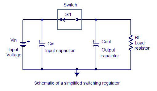
Switching regulators operate by drawing small amounts of energy from the input source and transferring it incrementally to the output. This is achieved using an electronic switch, which functions at a predetermined frequency, acting as a gate between the...
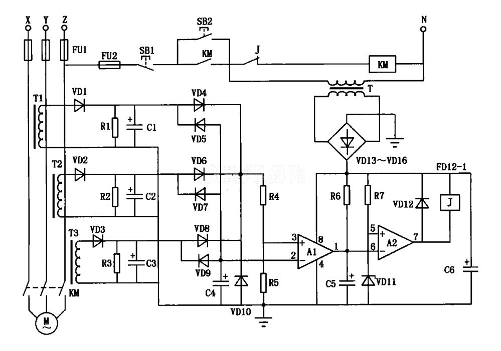
A current three-phase motor phase protection circuit is designed to detect three-phase current using homemade small current transformers T1, T2, and T3. The current signals are collected by rectifiers VD1, VD2, and VD3, while capacitors C1, C2, and C3...

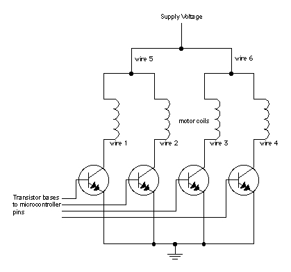
This document outlines the design process of a control circuit for a stepper motor. Given the characteristics of the stepper motor, the control circuit was developed as a state machine that transitions through four output states depending on two...
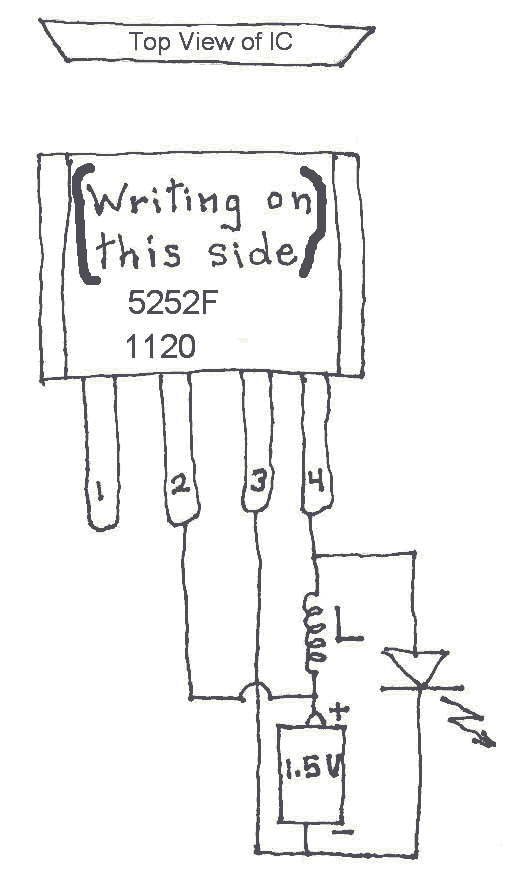
Many Joule Thief circuits traditionally rely on a bulky toroidal inductor that requires careful winding with copper wire. However, there are now compact 4-legged integrated circuits (ICs) available that can perform the same function using only a simple inductor,...