
A variable frequency oscillating circuit transistor
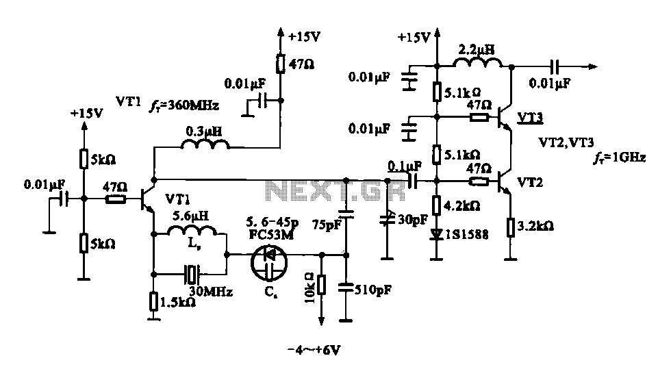
The variable frequency oscillator (VFO) circuit described operates at a frequency of 30 MHz, utilizing a combination of transistors and passive components to achieve its functionality. The core of the oscillator is transistor VT1, which is configured to form the primary oscillation circuit. The inductor (LP) connected to the emitter of VT1 plays a crucial role in determining the oscillation frequency in conjunction with the crystal resonator.
The use of varactor diodes in this configuration allows for frequency tuning. By varying the control voltage applied to the varactor diodes, the capacitance changes, which in turn alters the resonant frequency of the oscillator circuit. This tuning capability is essential for applications requiring precise frequency adjustments.
The circuit also includes a 75 pF capacitor, strategically placed in series between the emitter and collector of VT1. This capacitor helps to stabilize the oscillation and enhance the overall performance of the oscillator. The amplified output is taken from the collector of transistor VT3, which is part of a cascading amplifier stage that includes VT2. This multi-stage amplification ensures that the oscillation signal is sufficiently strong for further processing or transmission.
The overall design of the variable frequency oscillator circuit reflects a balance between stability, tunability, and amplification, making it suitable for high-frequency applications in various electronic systems. The careful selection of components and their arrangement is critical for achieving the desired performance characteristics, particularly in maintaining a stable oscillation while allowing for frequency adjustments through the control voltage applied to the varactor diodes.Fig variable frequency oscillator transistor circuit, which is mainly an oscillator, the crystal resonator and varactor circuit by the transistor diode, the output of the ampli fier, typically used to make high-frequency transistor oscillator. 30 MHz transistor circuit inductor LP is connected VT1 emitter circuit, it is connected in parallel and then in series with varactor diodes, and then with 75 p capacitor connected in series between the emitter and collector VT1. VT2, VT3 amplifier constituted after the oscillation signal is amplified by the VT3 collector electrode output.
Changes between V - + - 4 varactor control voltage.
Related Circuits
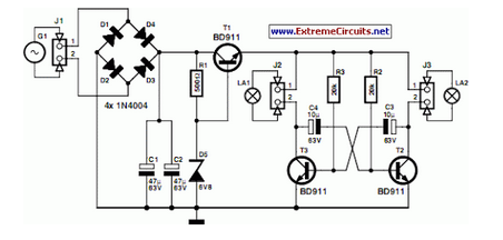
A front wheel with a built-in dynamo was purchased, providing a sine wave output of 30 Vpp at no load. Based on this, a simple power supply was designed using BD911 transistors, which are somewhat oversized for the application,...
The TA8210AH integrated circuit (IC) is designed for use as an audio power amplifier in car audio systems. Typically, car audio setups include subwoofers and woofers, as the confined space of a vehicle does not require excessively high sound...
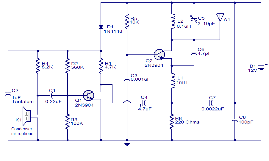
The FM transmitter circuit presented is both stable and simple. With an adaptive antenna, it can achieve a transmission range of approximately 200 meters. This transmitter was developed this year and has yielded positive results. The circuit operates using...
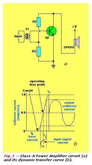
An audio power amplifier can enhance weak signals from devices like tuners, CD players, or tape decks to fill a room with sound. This article emphasizes the operating principles and circuitry of low-frequency power amplifiers utilizing bipolar junction transistors...
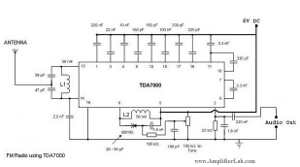
The following circuit illustrates a Single Chip FM Radio Circuit. This circuit is based on the IC TDA 7000 or TDA 7400. Features include a low-cost FM radio circuit. The Single Chip FM Radio Circuit utilizing the TDA 7000 or...
Temperature indicators and temperature-based products have garnered significant interest due to their numerous applications and various possible solutions, each presenting unique advantages and disadvantages. This concept focuses on a sensor interface that delivers high accuracy while minimizing board space....