
Transistor Tutorial Power Amplifiers Part 4
The audio power amplifier is a crucial component in audio systems, responsible for taking low-level audio signals and amplifying them to levels suitable for driving speakers. The operation of the amplifier is fundamentally based on the characteristics of the bipolar junction transistor (BJT), which serves as the primary active device in the amplification process.
In a Class A amplifier, the BJT operates in its linear region at all times, allowing for a smooth and continuous output signal. The quiescent current ensures that the amplifier is always ready to amplify incoming audio signals, but this constant current draw leads to inefficiencies, particularly at lower output levels. The design of the Class A amplifier prioritizes sound quality, making it ideal for applications where fidelity is paramount, despite its lower efficiency.
The Class B amplifier, on the other hand, utilizes a push-pull configuration where two BJTs operate out of phase. This design allows for higher efficiency, as the transistors only conduct during the positive or negative half of the input signal. However, this configuration introduces the potential for crossover distortion, which occurs when the output transitions between the two transistors. This distortion is particularly problematic in audio applications, where it can manifest as audible artifacts in the sound output.
To address the shortcomings of Class B amplifiers, the Class AB configuration combines elements of both Class A and Class B designs. By introducing a small forward bias to the transistors, the quiescent current is increased just enough to keep both transistors slightly conducting during idle periods. This approach minimizes crossover distortion while maintaining improved efficiency compared to Class A amplifiers.
In practical applications, careful attention must be given to the thermal management of power amplifiers, as transistors can generate significant heat during operation. Proper heat sinking and thermal design are essential to ensure reliable performance and longevity of the amplifier. Additionally, feedback mechanisms may be employed to further enhance linearity and reduce distortion, contributing to the overall sound quality of the audio system.
The choice of components, including the BJTs, transformers, and passive elements, plays a vital role in the performance characteristics of the amplifier. Selecting high-quality components can lead to better sound reproduction, lower noise levels, and increased reliability. As technology advances, newer amplifier designs and semiconductor technologies continue to evolve, offering improved performance metrics and greater efficiency while preserving the integrity of the audio signal.An audio power amplifier can boost weak signals from a tuner, CD player, or tape deck to fill a room with sound. This article focuses on the operating principles and circuitry of low-frequency power amplifiers based on the bipolar junction transistor (BJT).
Other articles in this series have discussed multivibrators, oscillators, audio preamplifie rs, and tone-control circuits, all based on the BJT. A transistorized audio power amplifier converts the medium-level, medium-impedance AC signal into a high-level, amplified signal that can drive a low-impedance audio transducer such as a speaker. A properly designed power amplifier will do this with minimal signal distortion. Audio can be amplified with one or more power transistors in either of three configurations: Class A, Class B, and Class AB.
Figure 1-a shows a single BJT Class A amplifier in a common-emitter configuration with a speaker as its collector load. A Class A amplifier can be identified by the way its input base is biased. Fig. 1-a shows that BJT Q1`s collector current has a quiescent value that is about halfway between the zero bias and cutoff positions.
(The quiescent value is that value of transistor bias at which the negative- and positive-going AC input signals are zero. ) This bias permits the positive and negative swings of the output collector AC current to reach their highest values without distortion.
If the AC and DC impedances of the speaker load are equal, the collector voltage will assume a quiescent value that is about half the supply voltage. The Class A circuit amplifies audio output with minimum distortion, but transistor Q1 consumes current continuously-even in the quiescent state-giving it low efficiency.
Amplifier efficiency is defined as the ratio of AC power input to the load divided by the DC power consumed by the circuit. At maximum output power, the efficiency of a typical Class A amplifier is only 40%, about 10% less than its theoretical 50% maximum.
However, its efficiency falls to about 4% at one-tenth of its maximum output power level. A typical Class B amplifier is shown in Fig. 2-a. It has a pair of BJTs, Q1 and Q2, operating 180 ° out-of-phase driving a common output load, in this example another speaker. In this topology, the BJTs operated as common-emitter amplifiers drive the speaker through push-pull transformer T2.
A phase-splitting transformer T1, provides the input drives for Q1 and Q2 180 ° out-of-phase. The outstanding characteristic of any Class B amplifier is that both transistors are biased off under quiescent conditions because they are operated without base bias. As a result, the amplifier draws almost no quiescent current. This gives it an efficiency that approaches 79% under all operating conditions. In Fig. 2-b, neither Q1 nor Q2 conducts until the input drive signal exceeds the base emitter zero-crossing voltage of the transistor.
This occurs at about 600 millivolts for a typical power transistor. The major disadvantage of the Class B amplifier is that its output signal is seriously distorted. THis can be seen from its dynamic transfer curve, also shown in Fig. 2-b. Audio distortion caused by the crossover between two out-of-phase transistors is annoying. To overcome this defect, the Class B amplifier is modified into the third category called Class AB for most high-fidelity audio equipment. Fortunately, Class B distortion can usually be eliminated by slight forward bias to the base of each transistor, as shown in Fig.
3-a. This modification sharply reduces the quiescent current of a Class B amplifier and converts it into a Class AB amplifier. Many early transistorized power amplifiers were Class AB, as shown in Fig. 3-a, but that circuit is rarely seen today. That circuit requires one transformer for input phase-splitting and another for driving the speaker, both costly electronics components.
In addition, electrical characteristics of both Q1 and Q2 m 🔗 External reference
Related Circuits
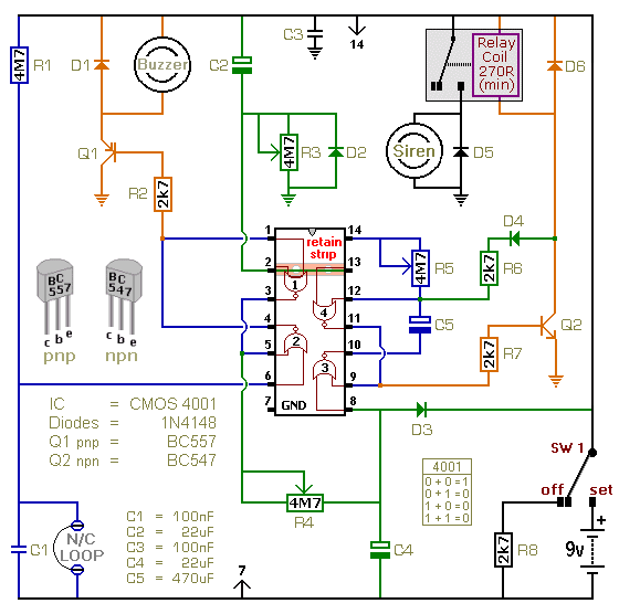
This is a single-zone alarm system featuring independently adjustable Exit, Entry, and Siren Cut-Off timers. It is designed to accommodate standard normally-closed input devices, such as magnetic reed contacts, foil tape, and passive infrared sensors (PIRs). The system can...
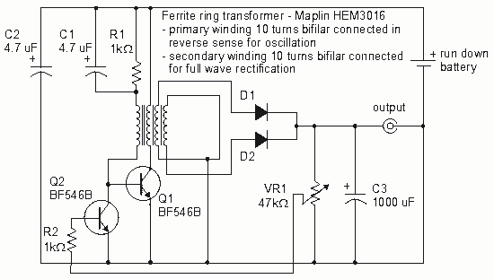
How to create a Joule Thief circuit to power a clock, including circuit details and tips for construction. The Joule Thief circuit is a simple and efficient boost converter that allows the extraction of usable voltage from low-voltage sources, such...
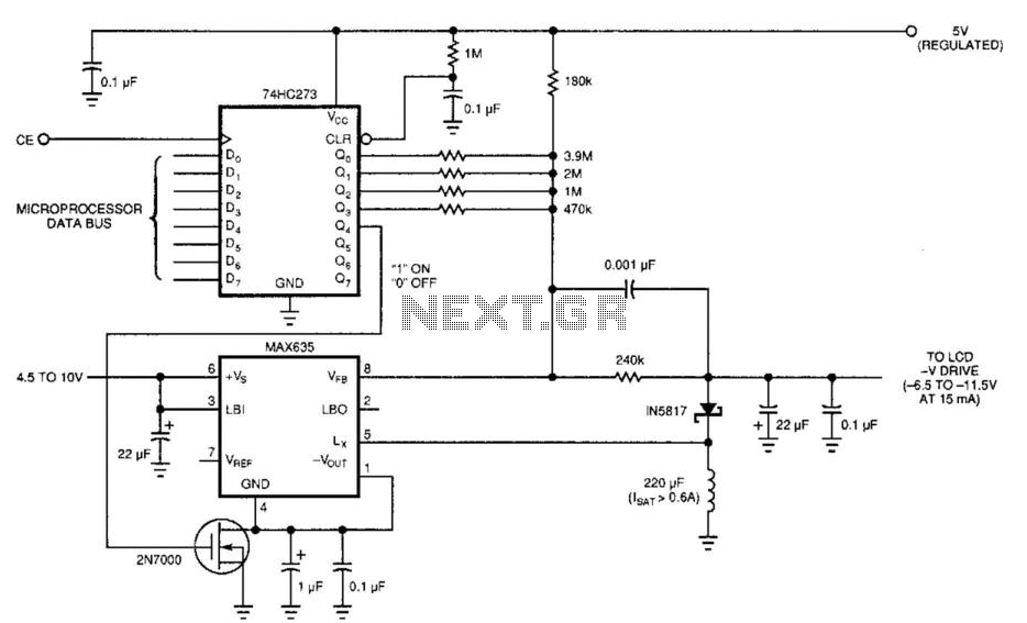
Laptop computers frequently utilize large-screen LCDs that require both a variable and a negative supply to achieve maximum contrast. This circuit operates from the system's positive battery supply and generates a digitally variable negative voltage to drive the display....

This is a 12V 100mA transformerless power supply designed for low current applications. C1 is an X-rated AC capacitor that reduces peak AC voltage. D1-D4 are diodes that rectify AC to DC, and C2 is used to filter out...
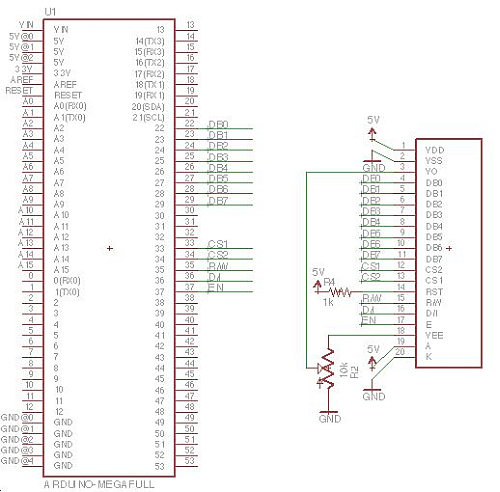
Displays are always beneficial. Until now, only 7-segment displays have been demonstrated for showing numbers using minimal resources. However, for displaying text or images, a simple LCD screen is required. There are basic LED screens available that operate on...
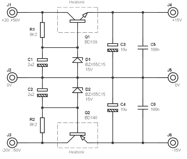
This circuit is designed to be integrated into an existing circuit, such as an audio amplifier, which already supplies symmetric voltages of +20V/-20V and +50V/-50V. The schematic diagram is derived from a dual polarity power supply circuit providing +/-...
Warning: include(partials/cookie-banner.php): Failed to open stream: Permission denied in /var/www/html/nextgr/view-circuit.php on line 713
Warning: include(): Failed opening 'partials/cookie-banner.php' for inclusion (include_path='.:/usr/share/php') in /var/www/html/nextgr/view-circuit.php on line 713