
200m fm transmitter simple circuit

The FM transmitter circuit is designed to provide reliable audio transmission over a moderate distance, making it suitable for various applications such as personal broadcasting or educational demonstrations. The use of a condenser microphone (K1) ensures high-quality sound capture, which is critical for effective transmission. Capacitor C1 plays a vital role in maintaining signal integrity by blocking any DC offset from the microphone, allowing only the AC audio signal to pass through to the base of the preamplifier transistor Q1.
Transistor Q1 is configured as a common-emitter amplifier, with resistors R2 and R3 establishing the necessary biasing conditions for optimal operation. The amplified audio signal present at the collector of Q1 is then coupled to the oscillator stage, which is realized with transistor Q2. The connection through capacitor C4 ensures that only the AC component of the signal is fed into Q2, allowing it to modulate the carrier frequency effectively.
The oscillation frequency is determined by the variable tank circuit formed by inductor L2 and capacitor C5. This configuration allows for fine-tuning of the transmission frequency, which is essential for avoiding interference with other radio signals. The feedback capacitor C6 is crucial for stabilizing the oscillation and ensuring consistent modulation.
Finally, the modulated FM wave is transmitted through antenna A1, which is designed to efficiently radiate the signal. The overall design emphasizes simplicity and stability, making it an accessible project for hobbyists and engineers alike. The circuit's capability to achieve a transmission range of about 200 meters with an adaptive antenna enhances its practical usability in various scenarios.FM transmitter circuit very stable and simple given here. With an adaptive antenna, the transmitter can reach a range of about 200 meters. Transmitter met this year and got a few good results. Let`s see how the circuit. A condenser microphone (K1) is used to collect the sound transmitted. The capacitor C1 is a DC decoupler and the audio signal is coupled to the base of Q1 which connects a preamplifier. R2 and R3 are the resistances of polarization of Q1. Amplified sound signal will be available at the collector of Q1 and, together with the emitter of transistor Q2 through capacitor C4 and inductor L1 1mH. C4 capacitor decouples the DC component of the preamplifier output. Q2 does the work of the oscillator and modulator. Inductor L2 and capacitor C5 variable tank circuit is necessary to create oscillations. Capacitor C6 is the feedback capacitor. The FM modulated wave will be available at the collector of Q1 and is transmitted through the antenna A1.
🔗 External reference
Related Circuits
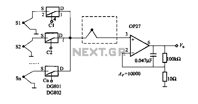
The electronic switch selection allows for multiple temperature control and monitoring points. It utilizes OP27 in conjunction with multiple S-type thermocouple circuits. The DG801/802 ultra-low on-resistance electronic switch has a maximum on-resistance of 0.40 ohms and operates under single-supply...
The industrial fuel oil furnace controller circuit consists of a power supply circuit, a testing and ignition control circuit, and a control implementation circuit, as illustrated in the accompanying diagram. The power supply circuit includes a step-down capacitor (C6),...
This light sensor switch circuit enables the automatic activation of a lamp when ambient light levels are low (such as during nightfall) and keeps the lamp illuminated for a specified duration. When transistors T4 and T5 are activated, the...
Advanced power control systems utilize electronic components such as thyristors for power switching, motor control, and other applications. These systems are involved in inverter design, lamp dimming, and speed control of motors. Triacs are the most commonly used semiconductor...
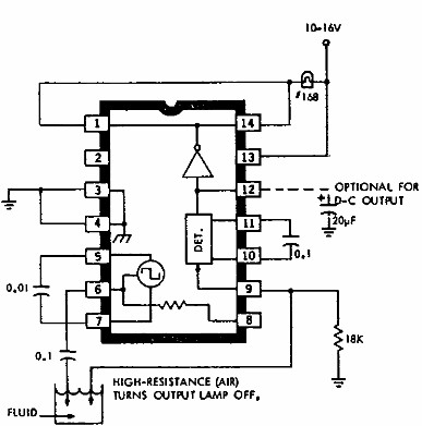
This electronic liquid detector circuit diagram utilizes the ULN2429A monolithic bipolar integrated circuit, which is designed to detect the presence or absence of various types of liquids. The detection mechanism involves comparing the resistance of a probe immersed in...
The objective is to transmit additional information through the distribution of articles. Please contact us via email at [email protected] within 15 days if there are any issues related to article content, copyright, or other concerns. Prompt action will be...