
A wireless color-changing decoration project

The described circuit utilizes a 555 timer in an astable configuration to generate a continuous square wave output, which serves as the clock signal for the shift registers. The frequency of operation is set to approximately 1 kHz, determined by the values of the timing resistors and capacitor connected to the 555 timer. The Reset pin (Pin 4) must be maintained in a high state to ensure proper functionality of the timer, preventing any unintended resets during operation.
The inclusion of a diode for in-circuit programming allows for flexibility in updating the firmware on the microcontroller without the need to physically remove it from the circuit board. This design choice minimizes the risk of damaging the microcontroller's pins during handling. The 4 MHz ceramic resonator provides a stable clock signal necessary for the microcontroller's operation, with its ground connection ensuring proper function.
The shift register's internal looping mechanism is facilitated by a resistor that allows data retention. The microcontroller's pin can override this loop when needed, enabling dynamic changes to the output data. The transition back to a high-impedance state allows for the new data to be processed without interference.
For the LED outputs, resistor values are critical in managing current flow to ensure consistent brightness across different colors. The choice of 220 ohms for red LEDs and 100 ohms for green and blue LEDs is based on the forward voltage characteristics of each LED type, achieving a target current of approximately 30 mA.
The DB9 connector serves as a robust interface for serial communication, with the Request To Send and Clear To Send pins tied together to ensure proper data flow control. The Data Terminal Ready and Data Set Ready pins are also interconnected, facilitating communication between devices. A protective resistor is employed to safeguard the TX433 module from the higher voltage levels typical of RS232 signals, while a diode protects against potential reverse voltage conditions.
The circuit also features a six-pin connector dedicated to in-circuit programming. This connector simplifies the reprogramming process by allowing access to the microcontroller's programming pins without the need for removal, thus enhancing the overall reliability and maintenance of the device. The ribbon cable connection provides a convenient method for interfacing with programming tools.So you`re either revved up about building one of these for yourself or you`re just reading on because you`ve nothing better to do. I can understand that. So let`s begin with a set of schematics: Don`t be confused by this - it`s your basic 555 timer configured as an astable multivibrator.
Its sole job is to provide pulses for the shift registers. T hese part values make the thing oscillate at around a kilohertz. Also fairly straightforward. Pin 4 is the Reset pin which should be held high for normal operation. The diode is to support in-circuit programming. Note that the crystal shown is actually a 4 MHz ceramic resonator with its center terminal tied to ground. The resistor allows the shift register to loop its information within itself, so long as the PIC`s pin does not decide to interfere.
When it does, however, the PIC`s pin is able to deliver enough current to `defeat` the looping information, thus overwriting it. Returning to a high-impedance state allows the new information to cycle some more. This circuit is repeated for each color. The value of the resistors are chosen to put about 30 mA through each LED, and adjusted to create approximately the same light output for full brightness.
For red I chose 220 ohms, and for green and blue 100 ohms. Again, this circuit appears once per color. This is your standard DB9 female connector, viewed from the solder side. This setup ties together the Request To Send and Clear To Send pins, and the Data Terminal Ready and Data Set Ready pins. The resistor is to protect the TX433`s input from the harsh RS232 voltage. The diode makes sure the TX433 never receives reverse voltage. The TX433 is powered by the Data Terminal Ready pin which provides ample current (even from my laptop).
You may have noticed that there is a six-pin connector on my circuit board - this is the in-circuit programming connector. I put it in so I wouldn`t have to remove the PIC from its socket every time I needed to reprogram it (which would have been a recipe for bent pins galore).
The hookup of the programming connector basically connects certain pins on the PIC to the same pins on a matching IC socket at the end of a sufficiently long ribbon cable. Just in case you`d like to build one of these, here is the hookup table: 🔗 External reference
Related Circuits
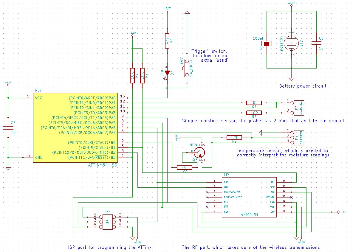
The goal is to create a final package that is as inconspicuous as possible, without any visible wires or adapters. This necessitates powering the project with a small battery. To conserve energy, the ATMega (or potentially the ATTiny) will...
This FM radio-controlled anti-theft system can be used with any device operating on a 6 to 12-volt DC power supply. The mini VHF FM transmitter is installed in the vehicle at night when it is parked in the driveway...
Upon acquiring the car, it was appreciated that it did not emit a "chirp" or sound the horn each time the doors were locked or unlocked. There are occasions when discreetness is preferred regarding entering or exiting the vehicle....
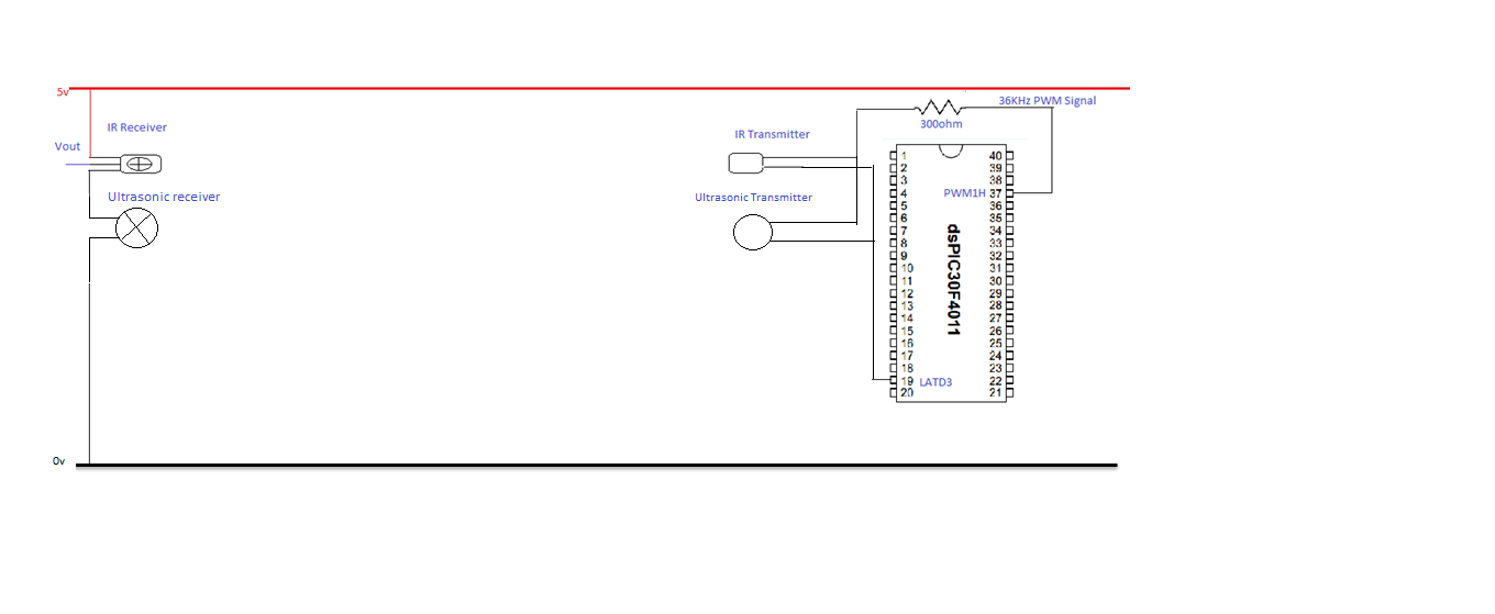
The objective of this experiment is to evaluate the range of the ultrasonic sensors (transmitter and receiver) utilized in this project. The sensor will be tested over a distance of 5 meters. The transmitter will be positioned directly facing...
The FM Wireless Microphone has gained popularity among both beginners and experienced constructors. It has been utilized in guitars and as a component of remote control systems. There have been numerous requests for a higher-powered circuit with improved microphone...

The infrared (IR) detector diode D1 captures the IR signal at approximately 40 kHz and transmits it to U1, a high-gain preamplifier, which then sends the signal to U2, a 4046 phase-locked loop (PLL) configured as a frequency modulation...