
Wireless Lock Tone
The circuit design described integrates several key components to achieve the desired functionality. The single-pole, double-throw (SPDT) switch allows for two distinct operational modes: one for auditory feedback via a buzzer and another for visual feedback through a flashing lamp. This dual feedback mechanism enhances user awareness of the locking status of the vehicle without the intrusive sounds typically associated with such systems.
The buzzer selected for this application is a low-decibel unit, ensuring that the sound is discreet yet audible enough to be heard from a short distance. The flashing lamp serves not only as a visual indicator but also as a diagnostic tool, illuminating when the circuit is energized, which aids in troubleshooting if the system fails to operate as intended.
The relay's removal and the subsequent wiring modifications indicate a thoughtful approach to circuit design, where simplification and reliability are prioritized. The use of solder to secure the wire shapes ensures longevity and stability in the connections, which is crucial in automotive applications where vibrations and environmental factors can affect performance.
The inclusion of an auxiliary fuse box for the stereo installation demonstrates an understanding of the vehicle's electrical system, allowing for organized and safe routing of wires. The use of a rubber port and plastic conduit illustrates best practices in cable management, protecting the wires from abrasion and environmental damage while maintaining a clean and professional installation appearance.
Finally, the Velcro attachment method for the buzzer, switch, and lamp enclosure provides flexibility for maintenance and adjustments, allowing the user to easily access the components as needed. This design effectively balances functionality, ease of use, and aesthetic considerations, making it a practical enhancement to the vehicle's locking system.When I got the car I was relieved that it didn`t "chirp" or blare the horn every time I locked or unlocked the doors. Let`s face it, there are times when we don`t want our comings and goings announced in such a tactless manner.
Still, I found that in the daytime, when walking away from the car, or after forgetting until I`m some distance away, I c ould not tell if the car was locking or unlocking. I found on the crossfireforum. org website an idea to install a device that gives out a gentle tone that can be heard from a short distance and does not announce the locking or unlocking like the opening of a Broadway musical. The circuit I designed has a single-pole, double throw push-button switch. In one position, the buzzer in the circuit quietly beeps. In the other position, the lamp in the circuit flashes. The reason for the lamp is to provide a diagnostic function to aid in troubleshooting if problems develop.
I mainly put the switch in to provide an easy way to disable the beeping sound if for some reason I didn`t want it to operate. I removed the relay and wrapped the wires around the 85 terminal (positive) and 86 terminal (negative).
After shaping the wires, I removed them and put some solder on them to help them keep their shape. Then I replaced the wires on their respective terminals, and reinstalled the relay in its socket. Here is a view of the wiring coming from the relay in the upper right corner of the picture. Black is ground and white is positive. Note the thicker red wire coming off the fuse bank. This is the switched positive lead that goes to the auxiliary fuse box I assembled and installed in support of my stereo install. I took this opportunity to route the red stereo wire and the leads for the buzzer through a rubber port provided for this purpose.
The wires go into some plastic conduit that I installed to help keep the wires protected and dressed. Here`s another shot of the port with a white wire coming out of it. The port slides out of the fuse case and can be easily handled to cut the holes and feed the wires through.
Then the rubber port can be reinstalled onto the fuse case. Take care to get the rubber parts properly slotted on both sides of the case wall for proper sealing. The box containing the buzzer, switch and lamp is Velcro`d onto the fuse panel cover and allows me to activate or deactivate the tone alert by pressing the switch.
🔗 External reference
Related Circuits
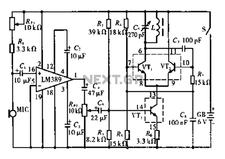
This circuit is tested and functional. The LM389 integrated circuit serves as the core element, where the voice channel number is acquired by the microphone (MIC) and converted into electrical signals. These signals are amplified by the volume control...
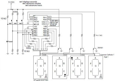
A digital clock project utilizing the PIC16C54 microcontroller can be constructed using the provided circuit diagram. This electronic project features a straightforward time-of-day clock that includes four seven-segment LED displays and three input switches, along with an additional reset...
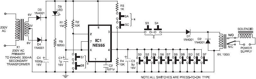
A simple electronic key code lock circuit that requires few external components can be constructed using this schematic diagram. This electronic key code lock circuit is based on a common 555 timer circuit and other standard components. This low-cost...
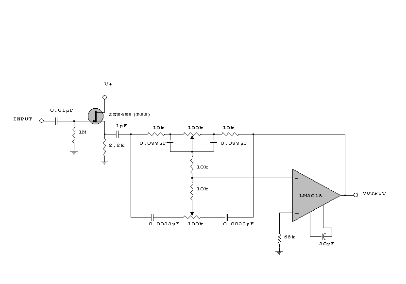
This circuit is a simple series tone control circuit. It utilizes the surgical amplifier LM301A. The JFET 2N3684 provides high input impedance and low noise for the unbuffered operational amplifier, which operates in an equalizer (EQ) configuration. Further details...
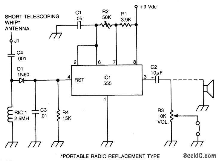
A sidetone oscillator is a specialized audio oscillator that is activated and deactivated in conjunction with the transmitter. This oscillator is driven by RF signals and is powered by batteries. It employs a 555 integrated circuit (IC) timer configured...
After working with an LCD, driving LED segments becomes relatively straightforward, so programming should not be a major concern. The 20M circuit mentioned earlier includes code and a schematic. The forum receives various educational inquiries, especially close to submission...
Warning: include(partials/cookie-banner.php): Failed to open stream: Permission denied in /var/www/html/nextgr/view-circuit.php on line 713
Warning: include(): Failed opening 'partials/cookie-banner.php' for inclusion (include_path='.:/usr/share/php') in /var/www/html/nextgr/view-circuit.php on line 713