
AB4YD Amateur Radio Page
This project implements a single-band amateur radio transceiver, primarily designed for operation on the 80-meter band. The circuit architecture is centered around the use of 6V6 tubes, which are known for their reliability and performance in RF applications. The regulated voltage supply ensures consistent operation and minimizes the risk of frequency drift, which can be a common issue in older designs.
The VFO (Voltage-Frequency Oscillator) is a critical component in this design. Initially conceived within a coffee can for stability, the decision to move it to a separate chassis was pivotal in addressing microphonic issues that arose from vibrations and mechanical noise. The use of a 6C4 tube for the VFO not only helps to reduce heat generation but also contributes to improved frequency stability, which is crucial for maintaining signal clarity during transmission.
The addition of the 6AC7 stage serves to amplify the output signal before it reaches the final amplification stage, which employs an 807 tube. This stage is responsible for driving the antenna and achieving the desired transmission power. The design operates with a B+ voltage that is lower than typical, which may account for the reduced output power observed. Nevertheless, achieving approximately 20 watts into a 50-ohm load is a respectable performance for this type of rig, especially considering the constraints of the power supply.
The implementation of a half-frequency VFO allows for efficient doubling of the frequency, enhancing the overall performance of the transmitter. This approach not only simplifies the design but also improves the harmonic characteristics of the output signal, which is essential for compliance with amateur radio regulations.
In summary, this transceiver project exemplifies a blend of traditional design principles with modern adaptations, resulting in a functional and stable amateur radio rig suitable for 80-meter operations. The iterative improvements made throughout the design process reflect a commitment to enhancing performance while addressing practical challenges encountered during development.This project was inspired by a series of QST articles by Hayward, W1PH. I based my rig on his April 1962 article, "Have You Tried 160 Lately ". I liked his simple, single band rig. I thought his use of 6V6 tubes, along with regulated voltages, to be a simple but stable alternative to being "rock bound". You can read about his "coffee can" VFO, in the August `49 and Sept `51 issues of QST. However, I ignored his approach to mounting the VFO part of the circuit in a sturdy coffee can, and just put all of the circuits onto the same chassis. It worked, but it was very microphonic, and this made it difficult to operate. I eventually chose another route for the VFO, and used a separate chassis for the VFO circuit. Along the way, I also changed the VFO tube to a 6C4, mainly to reduce problems related to heat. The output was very low, so I added a 6AC7 stage. I also went to a 1/2 freq VFO, and doubled the frequency to 80M just in front of the 807 final. I am pretty happy with the stability of the VFO. The output from the 807 seems a little low, but perhaps it is due to my low B+ and 250V screen. I get about 20 watts into my 50 ohm antenna, even after going thru my half-wave output filter. All in all, it was a fun project. 🔗 External reference
Related Circuits
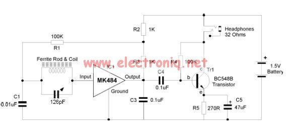
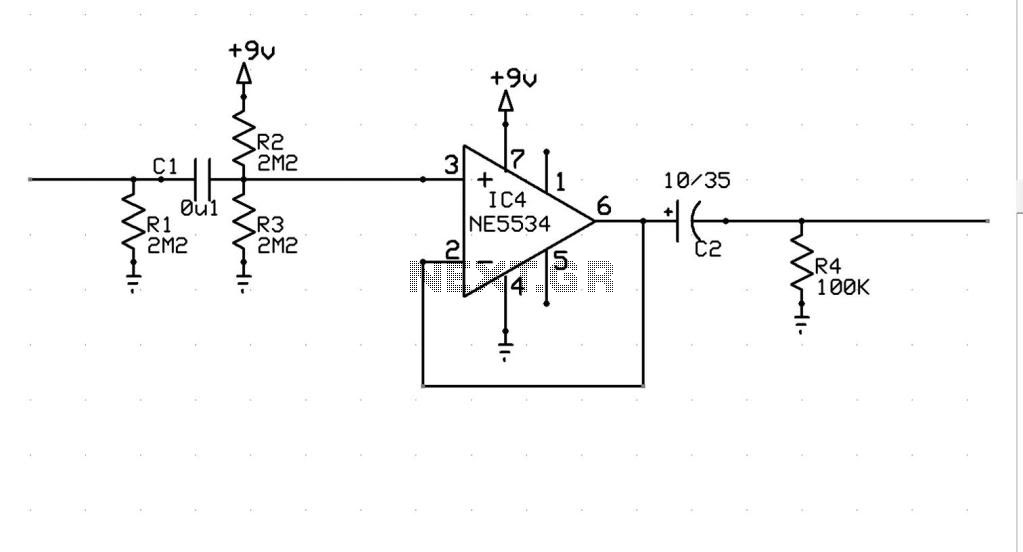
The MK484 AM radio circuit offers a comprehensive solution that includes an RF amplifier, detection, and automatic gain control (AGC) circuit. It requires only a few external components to achieve a high-quality AM tuner. The circuit features an input...
The ZN414 is an economical, single-chip AM radio integrated circuit introduced in 1972 by Ferranti. The TDA7000 is a monolithic integrated circuit designed for mono FM portable radios or receivers, focusing on minimizing size. Additionally, there is an FM...
Visit eBid United Kingdom, the online marketplace without fees - buy and sell today. eBid United Kingdom serves as an online marketplace that facilitates buying and selling transactions without imposing fees on its users. This platform offers a user-friendly interface...
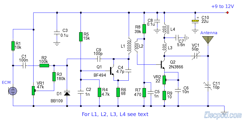
The AM signal is captured by the antenna, 10 mt long horizontal wire, WELL insulated from earth. The inductor and capacitor form a resonator, that will tune with the station whose frequency is F = 1 / (2 *...
Most surviving TR-1 radios no longer function. Many collectors prefer to maintain them in their original condition to preserve authenticity. However, there may come a time when one wishes to hear the radio play. Before proceeding with any modifications,...
This metal detector schematic circuit is based on a transistor radio as a detector. This metal detector is entirely different from other metal detectors because this circuit does not have a speaker. With the radio tuned to a weak...