
Metal detector using radio frequency
The described metal detector circuit utilizes a radio receiver as a primary detection mechanism, distinguishing it from conventional metal detectors that typically employ audio output for indication. The operational principle hinges on the interaction between the radio's tuner and the locator oscillator, which is affected by the presence of metal. The circuit configuration allows for the detection of metal objects through frequency modulation, where the inductance of the L1 coil plays a crucial role.
The L1 coil, composed of 18 turns of 0.65 mm enameled wire, serves as the search coil for the metal detector. The choice of wire gauge and the number of turns is critical, as it directly influences the sensitivity and detection range of the device. The coil is wound on a 4-inch diameter support, ensuring optimal performance for detecting various metal types.
Powering the circuit requires a stable 9-volt DC supply, which can be sourced from either a battery or an external power supply. This voltage level is suitable for the components used, particularly the Q1 transistor, which can be replaced with an equivalent NPN transistor if necessary. The circuit components, including the resistors, are specified to be ½ watt to ensure they can handle the power without overheating.
Capacitance values are equally important, with C1 acting as a variable capacitor that allows for fine-tuning of the circuit's sensitivity to metal detection. The inclusion of C2, a 100 pF silver mica capacitor, C3, a 0.05 µF disc capacitor, and C4, a 4.7 µF capacitor, contributes to the overall stability and performance of the oscillator circuit, ensuring reliable operation.
Overall, this metal detector design presents a unique approach to metal detection, leveraging the principles of radio frequency modulation and providing a compact, efficient solution for identifying metallic objects.This metal detector schematic circuit is based on a transistor radio as an detector .This metal detector is total different that other metal detectors, because this circuit doesn't have a speaker . With the radio tuned to a weak station you must adjust the variable capacitor C1 until the locator oscillator beats against the received signal .
If a metal is detected the inductance of the L1 coil is changed , changing the frequency of the locator oscillator’s , resulting a change in the beat tone radio .
The L1 search coil of the metal detector circuit must have 18 turns from a 0.65 mm enameled wire scrambled on a 4 inch diameter support . This metal detector circuit needs to be powered using a 9 volts power supply ( DC) or a 9 volts battery .
The Q1 transistor can be RCA SK3011 npn transistor or equivalent type and all resistors need to be ½ watts . The C1 capacitor is a variable capacitor with a value of 365 pF , C2 is a 100pF silver mica capacitor , C3 is a 0.05 uF disc capacitor and the C4 is a 4.7 uF capacitor .
🔗 External reference
Related Circuits
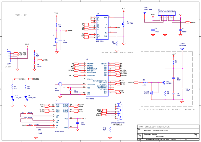
IperCODE is an educational project that enables the construction of a remote control acquisition system utilizing rolling code technology. It allows for the transmission of the received code via an RS232 serial port, the visualization of the code on a...
This circuit was designed to detect when a call is incoming in a cellular phone (even when the calling tone of the device is switched-off) by means of a flashing LED. The device must be placed a few centimeters...
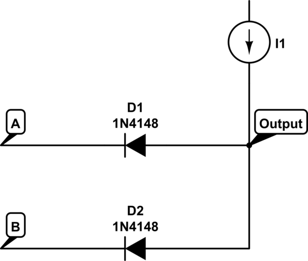
The voltage at the anode and cathode of the diodes is checked to determine whether they are conducting. There is confusion regarding the current source and how to determine the state of the diodes for input combinations (00, 01,...
This circuit utilizes a 1458 dual op-amp to create a radar detector. C1 serves as the radar signal detector. The first op-amp functions as a current-to-voltage converter, while the second op-amp buffers the output to drive the piezo transducer....
The frequency doubler utilizes a single integrated circuit (IC). Similar to other frequency doublers, this circuit leverages both the rising and falling edges of the input signals to generate digital pulses, effectively doubling the input frequency. In the absence...
A wideband RF detector is being designed, utilizing a series of resonant LC tanks spaced between 5 to 10 MHz apart, with an exception of 1 MHz spacing from 9 MHz onwards. The design of a wideband RF detector incorporating...