
Regency TR-1 Transistor Radio
1. Carefully unsolder tabs 3 and 4, pulling the board away from the chassis while ensuring the fine antenna wire remains attached.
2. Separate the chassis and PC board, keeping the antenna wire and volume control wires attached. Restoration of electrical connections will be necessary using clip leads between the PC board solder points and the chassis during repair and testing.
3. Inspection of the foil side of the PC board revealed damage, which was cleaned and repaired using 30 gauge wire-wrap wire. It was noted that a green wire had been used to substitute for a damaged trace.
4. The repairs required depend on the specific issues present. Based on experience, electrolytic capacitors were suspected to be problematic. Out of four capacitors, two were found to be shorted, one was open-circuited, and one was functioning properly. All four capacitors were replaced with new components, with values not being overly critical. For instance, 5uF/25V and 2uF/3V capacitors were replaced with 4.7uF/50V, and the two 40uF/3V capacitors were replaced with 47uF/25V. Careful attention to polarity was emphasized before removing the old capacitors.
5. The on-off switch was also identified as faulty. Since it consists of two metal pieces that make contact, a screwdriver was used to scrape away dirt from the contact points, effectively resolving the issue. Additionally, the battery clip was adjusted for a tighter fit, and the switch contacts in the earphone jack were cleaned.
6. Important test points within the radio were identified, including connections to the AVC (Automatic Volume Control) line, the IF (262 kHz Intermediate Frequency) signal, and audio signals before and after the AF (Audio Frequency amplifier) stage, located at the top of the volume control and at the speaker, respectively. The ANT and OSC trimmers were configured as believed to be correct. While various coils are not depicted, the oscillator coil is recognized as the one without a metal can, while the others are the IF transformers.
7. Although other components may potentially fail, it is less likely. If replacing the capacitors does not resolve the issues, further troubleshooting will be needed, guided by the documentation referenced. The final appearance of the radio is shown, with yellow lines indicating the new capacitors and highlighting a replacement transistor previously installed.Most surviving TR-1s no longer work. Many collectors (such as myself) prefer to keep them in "as-manufactured" condition. That way the authenticity is preserved. But at some point, you may be anxious to hear one play. Before you start soldering, ask one question - DO I REALLY WANT TO DO THIS Once it`s changed, it`s no longer original, and you may end up with a "modified" radio, and still have one that doesn`t work! NOTE - I`m presenting the information below to document what I did. Unfortunately I`m really not in a position to fix radios belonging to others. There are people who do specialize in fixing "antique" and collector radios and you should be able to track some down on the web or in newsgroups. But unless you have significant experience with electronics repair, I would think carefully about doing it yourself.
When I bought my ivory TR-1, I discovered that it had been modified. So I figured, "well, it`s not authentic anymore anyway, so now I`ve got my `experimenter` radio". The first clue was when I spotted a replacement oscillator/converter transistor, X1. The "new" one was a GE 2N168A, which dates back pretty far. It "wiggled" when I touched it - a bad sign, indicating the foil PC board trace into which it was soldered was probably pulled away from the board. This happens when too much heat is used in soldering. I was going to need good documentation of how the radio should appear, where the parts go, and suggested schemes for doing the repair.
Here`s what I used (if you need higher resolution jpg files of these, let me know): 6. Unsolder (go easy with this) tabs 3 and 4. Pull the board away from the chassis as you do this, but be careful with the fine antenna wire that should remain attached. 7. Pull the chassis and PC board apart. The antenna wire and the volume control wires stay attached. Because you desoldered the two tabs, the equivalent electrical connection will have to be restored with clip leads between the PC board solder points and the chassis during repair and testing.
You can see the damage on the foil side of my PC board. I cleaned that up and replaced some traces with 30 gauge wire-wrap wire. Note that someone had substituted a green wire for a damaged trace. The repairs to be made to the circuit depend on what`s wrong, and following the PF Reporter article should track things down. My own feeling is that the likely culprits are probably the electrolytic capacitors. I found two of my four to be shorted, one open circuited, and the other one working properly. I replaced all four. The exact values are not too critical. For example, I replaced them as follows: 5uF/25V and 2uF/3V each with new 4. 7uF/50V. And the two 40uF/3V with new 47uF/25V. Pay close attention to the polarities before removing the old ones. I also discovered the on-off switch to be bad. This is just two pieces of metal that touch, so I took a screwdriver and used the edge of it to scrape away any dirt from the contacting parts of the switch.
That fixed it. I also bent the battery clip a little tighter, and cleaned the "switch" contacts in the earphone jack. There are various important test points in the radio. The photo shows connections to the AVC (Automatic Volume Control) line, IF (262 kHz Intermediate Frequency) signal, and audio before and after the AF (Audio Frequency amplifier) stage (at the top of the volume control, and at the speaker, respectively).
The ANT and OSC trimmers are shown as I believe they are configured. The various coils are not shown, but the one without the metal can is the oscillator coil, and the others are the IF transformers. While it`s possible for other parts to be bad, it`s probably less likely. However, if "re-capping" the radio doesn`t fix it, then the troubleshooting article should help. Here`s what the radio looked like after I was finished. The yellow lines point to the new capacitors, and to somebody`s replacement transistor (some time 🔗 External reference
Related Circuits
The TDA7000 is a well-known FM radio receiver integrated circuit (IC), also referred to as a one-chip FM radio receiver. It operates within the VHF FM band, covering frequencies from 70 to 120 MHz. Introduced in the 1980s, the...
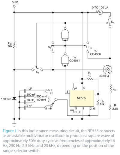
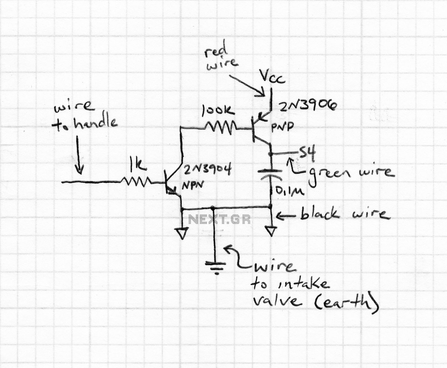
Bipolar junction transistors transfer a current from a lower-resistance emitter to a higher-resistance collector. This property can be utilized to measure inductance. Bipolar junction transistors (BJTs) are semiconductor devices that play a crucial role in electronic circuits by enabling the...
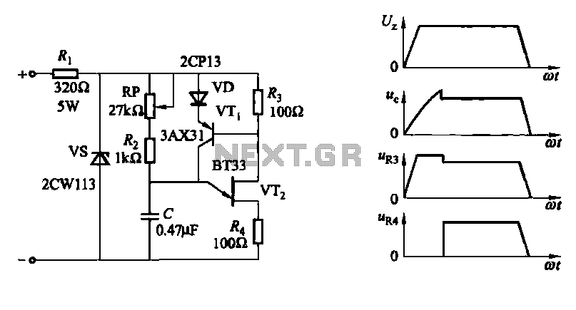
A conventional single junction transistor trigger circuit is limited to producing narrow pulses due to the rapid turn-off characteristics of the single-junction transistor. To address this limitation, a PNP transistor is added to the single-junction transistor trigger circuit, which...

This is a simple interface box designed to connect a radio to a PC, featuring several enhancements compared to similar projects widely available. Such interfaces are utilized to manage the transmission and reception of digital signals (RTTY, BPSK, and...
This circuit illustrates the high and mid-frequency sections of a car radio. The medium wave band I operates within the frequency range of 520 to 950 kHz, while Poland II operates between 900 and 1640 kHz. The circuit employs...
The most commonly available headphones have an impedance of 2 × 32 Ω. This relatively low value makes them unsuitable for certain designs. However, with some clever modifications, these headphones can be adapted for such applications. To achieve this,...