
Absolute value amplifier
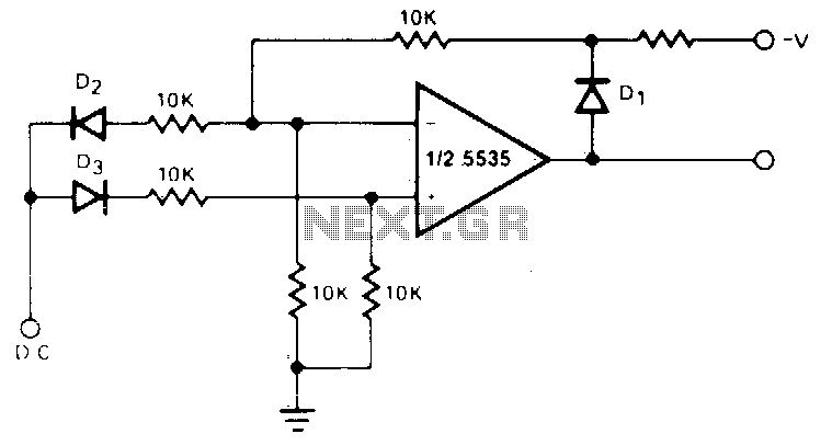
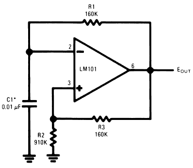
This circuit utilizes operational amplifiers (op-amps) to achieve its functionality. The non-inverting amplifier configuration is employed for positive input signals, where the output voltage is a scaled version of the input voltage, determined by the feedback and input resistors. The gain of this configuration can be set using resistors R1 and R2, following the formula: Gain = 1 + (R2/R1).
For negative input signals, the circuit switches to an inverting amplifier configuration. In this mode, the input signal is applied to the inverting terminal of the op-amp, and the output is inverted and scaled based on the same resistor values. The gain for the inverting configuration is given by the formula: Gain = -(R2/R1), leading to a negative output voltage that corresponds to the negative input.
The circuit's performance, particularly its accuracy for input voltages below 1V, indicates limitations in the op-amp's specifications or the design itself. Factors such as the op-amp's input offset voltage, bias current, and noise characteristics can significantly affect the output for low voltage signals. In applications where precision is not critical, this circuit can still provide a useful amplification function, making it suitable for various signal processing tasks where high fidelity is not required.
Design considerations should include selecting an op-amp with suitable characteristics for the intended application, ensuring power supply levels are adequate to accommodate the expected output range, and carefully choosing resistor values to optimize gain while maintaining stability and minimizing distortion. Additionally, implementing bypass capacitors on the power supply pins can enhance performance by reducing noise and improving transient response.The circuit generates a positive output voltage for either polarity of input. For positive signals, it acts as a noninverting amplifier and for negative signals, as an inverting amplifier The accuracy is poor for input voltages under 1V, but for less stringent applications, it can be effective. 🔗 External reference
Related Circuits
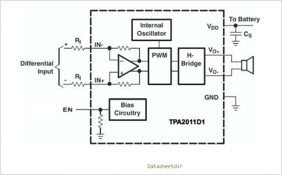
The TPA3007D1 is a 6.5-W mono bridge-tied load (BTL) class-D audio power amplifier featuring high efficiency, which eliminates the need for heat sinks. This amplifier can drive 8-ohm speakers with only a ferrite bead filter required to reduce electromagnetic...
This small amplifier was intended to be used in conjunction with an electric guitar to do some low power monitoring, mainly for practice, either via an incorporated small loudspeaker or headphones. The complete circuit, loudspeaker, batteries, input and output...
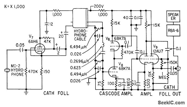
A cathode-follower hydrophone isolation amplifier and high-gain preamplifier are used to feed the Navy RBA-6 low-frequency radio receiver on a trawler. This setup is designed to receive a modulated 21-kc beam that transmits data regarding trawl net depth. The...
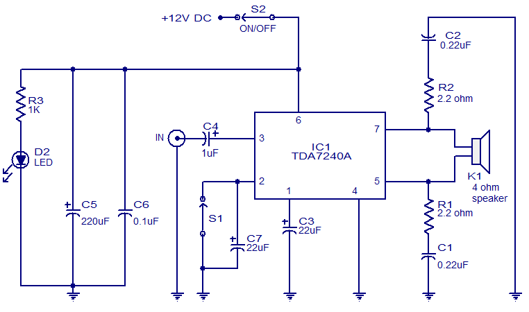
The audio amplifier presented here is based on the TDA7240 integrated circuit from ST Microelectronics. The TDA7240 is capable of delivering 20 watts of audio output power into a 4-ohm load. It requires a minimal number of external components...
The timing capacitor (C1) generates multiple time constants, facilitating substantial voltage fluctuations at the input, attributable to the LM101's extensive input voltage range. It is advisable to decrease the value of resistor R2 and to increase the capacitance of...
This is a specialized low-voltage version of an audio preamplifier. The emitter voltage of transistor T1 is biased close to half the supply voltage (1.5V) to enable maximum output voltage swing. Both transistors are directly coupled and utilize closed-loop...
Warning: include(partials/cookie-banner.php): Failed to open stream: Permission denied in /var/www/html/nextgr/view-circuit.php on line 713
Warning: include(): Failed opening 'partials/cookie-banner.php' for inclusion (include_path='.:/usr/share/php') in /var/www/html/nextgr/view-circuit.php on line 713