
operational amplifier op amp oscillator
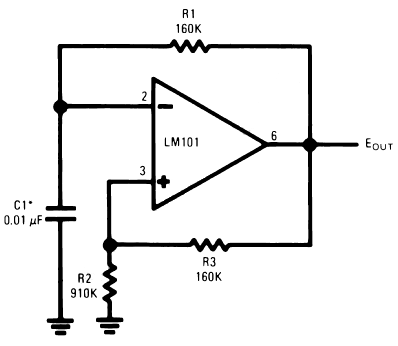
The circuit incorporates a timing capacitor (C1) that plays a crucial role in shaping the response of the system by producing multiple time constants. This is particularly significant in applications where the LM101 operational amplifier is employed, as it is designed to handle a wide input voltage range. The proper selection of C1 is essential to ensure that the circuit operates within safe limits and maintains stability during operation.
R2 serves as a critical component in determining the charging and discharging rates of C1. A reduction in the resistance value of R2 will lead to faster time constants, enhancing the responsiveness of the circuit to input voltage changes. Conversely, if R2 is too high, the system may become sluggish, failing to adequately respond to rapid voltage swings.
The smaller polarized capacitors included in the design are strategically connected to the positive supply voltage. This configuration is essential, as these capacitors help to stabilize the circuit while allowing the larger timing capacitor (C1) to manage significant voltage variations effectively. By ensuring that these smaller capacitors are not grounded, the circuit can maintain a consistent reference point, which is vital for accurate signal processing.
In summary, the interplay between C1, R2, and the smaller polarized capacitors is fundamental to achieving optimal performance in circuits utilizing the LM101. Careful consideration of component values and configurations will ensure that the circuit operates reliably within its specified parameters, ultimately leading to improved functionality and performance in electronic applications.Timing capacitor (C1) produces several times constants which is used to allow large voltage swings on the input due to the LM101`s large input voltage range. The R2 should be reduced and the C1 should be increased to keep from exceeding these ratings. The smaller polarized capacitors is still used by returning them to positive supply voltage inste ad of ground, even though C1 requires the large values. 🔗 External reference
Related Circuits
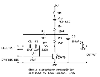
The circuit is a simple one-transistor amplifier with an amplification factor of approximately 30-40 dB, which varies depending on the transistor, temperature, and voltage. The dynamic microphone input is a straightforward one-transistor amplifier circuit with no special features. LED...
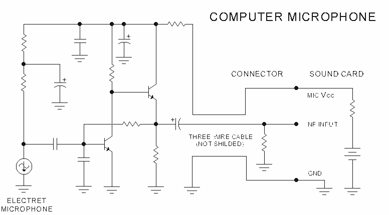
The sound card for a PC generally has a microphone input, speaker output and sometimes line inputs and outputs. The mic input is designed for dynamic microphones only in impedance range of 200 to 600 ohms. Lazar has adapted the...
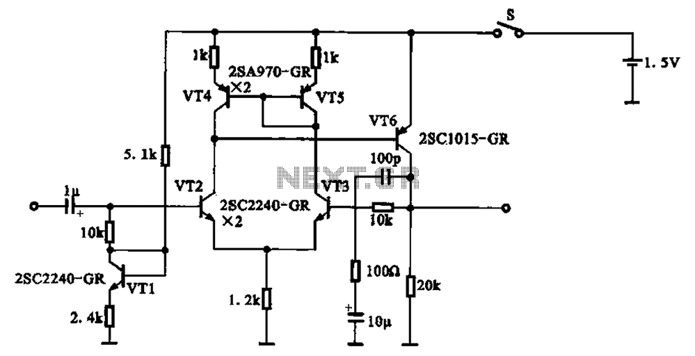
A 1.5V-powered microphone signal amplifying circuit is designed with a power supply for the microphone signal amplification. The circuit primarily consists of a differential amplifier formed by transistors VT2 and VT3. Additionally, VT6 functions as a common emitter voltage...
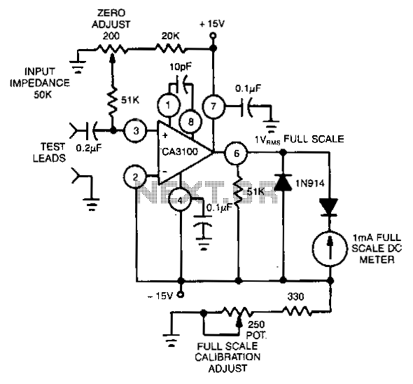
This circuit utilizes the CA3100 BiMOS operational amplifier to drive a 1-mA meter movement to its full scale with a 1-V RMS input. The circuit configuration incorporates the CA3100 BiMOS operational amplifier, which is known for its high input impedance...
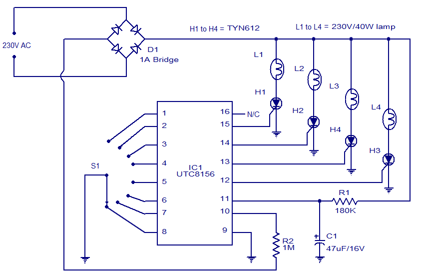
This 8-function serial Christmas lamp controller is based on the IC UTC 8156 from Unisonic. Specifically designed for this purpose, the UTC 8156 can control four lamps in eight modes: waves, sequential, slo-gol, chasing/flash, slow fade, twinkle/flash, steady ON,...

Function generators are essential in the design, testing, and operation of encoders, modulators, demodulators, and measurement instruments. This document presents an economical method to construct a bus-controlled sinewave oscillator that exhibits exceptionally low distortion. The circuit produces a sinusoidal...
Warning: include(partials/cookie-banner.php): Failed to open stream: Permission denied in /var/www/html/nextgr/view-circuit.php on line 713
Warning: include(): Failed opening 'partials/cookie-banner.php' for inclusion (include_path='.:/usr/share/php') in /var/www/html/nextgr/view-circuit.php on line 713