
AC-coupled differential amplifier PGA202
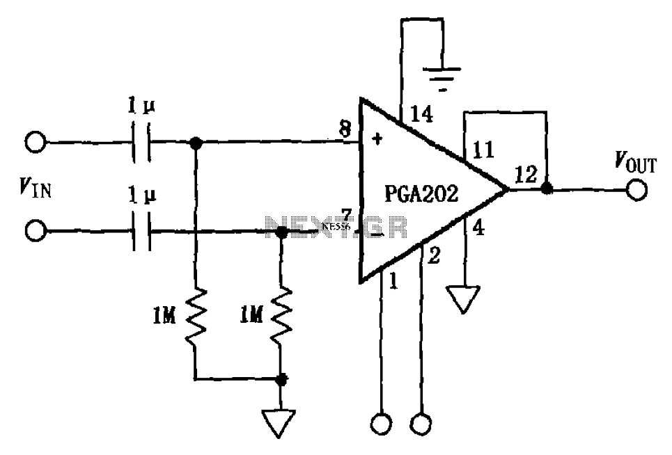
The PGA202 circuit operates as a differential amplifier designed for high-performance applications, particularly in audio and signal processing. The AC coupling is achieved using the two 1 µF capacitors, which effectively block any DC offset present in the input signal while allowing AC signals to pass through. This is crucial in maintaining signal integrity and preventing saturation of the amplifier.
The two 1 MΩ resistors form a voltage divider with the capacitors, setting the input impedance of the circuit and determining the low-frequency response. The calculated cutoff frequency of approximately 0.16 Hz indicates that signals below this frequency will be attenuated, while higher frequency signals will be amplified. This characteristic is essential for filtering out unwanted low-frequency noise, ensuring that only the desired AC signals are processed by the amplifier.
In practical applications, the output of the PGA202 can be connected to further signal processing stages, such as additional amplification or filtering circuits. The design is particularly suitable for audio applications, where maintaining the fidelity of the signal is paramount. The use of high-value resistors and capacitors allows for a compact design while achieving the necessary performance specifications. As shown in FIG PGA202 constituted by AC-coupled differential amplifier. The circuit at the input PGA202 plus two 1 F capacitors and two 1M resistor composition frequency 0.16H z above Qualcomm AC coupling circuit, after the AC signal input differential amplifier PGA202 output.
Related Circuits
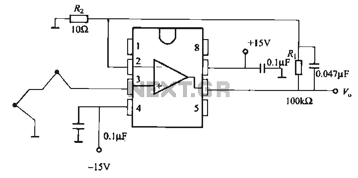
The OP07 is a low drift operational amplifier with a maximum voltage drift of 30 µV/°C and a maximum drift of 0.6 mV/V/°C. It features low noise characteristics with a maximum noise level of 0.6 pV/√Hz, offering ultra-stability with...
This is a schematic diagram of a stereo audio amplifier for a car. The circuit is powered by a single IC, the TDA1553, along with some external components. This IC is designed to manage the stereo car audio system....
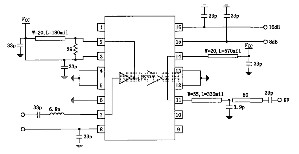
The circuit diagram illustrates the application of a 915MHz RF2155 power amplifier. The radio frequency (RF) signal enters through pin 7, where it is processed by a preamplifier. The output from the preamplifier is further amplified by the power...
This circuit was submitted by Graham Maynard from Newtownabbey, Northern Ireland. It has an exceptionally fast high-frequency response, as demonstrated by applying a 100kHz square wave to the input. All graphs were produced using Tina Pro. The circuit in question...
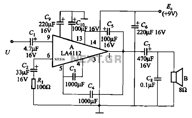
Audio power amplifier circuit utilizing the LA4112 integrated power amplifier along with additional components as shown in the figure. The audio power amplifier circuit based on the LA4112 integrated power amplifier is designed to deliver high-quality audio amplification for various...
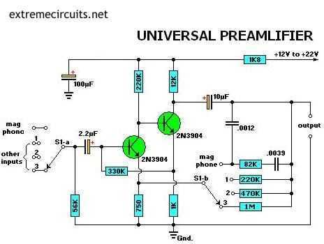
Most audio amplifier systems must have preamplifiers with many different characteristics. These include high-gain linear response for magnetic microphones, low-gain linear response for tuners, and high-gain RIAA equalization for magnetic phone cartridges. To meet this broad requirement, most amplifier...
Warning: include(partials/cookie-banner.php): Failed to open stream: Permission denied in /var/www/html/nextgr/view-circuit.php on line 713
Warning: include(): Failed opening 'partials/cookie-banner.php' for inclusion (include_path='.:/usr/share/php') in /var/www/html/nextgr/view-circuit.php on line 713