
AC motor control
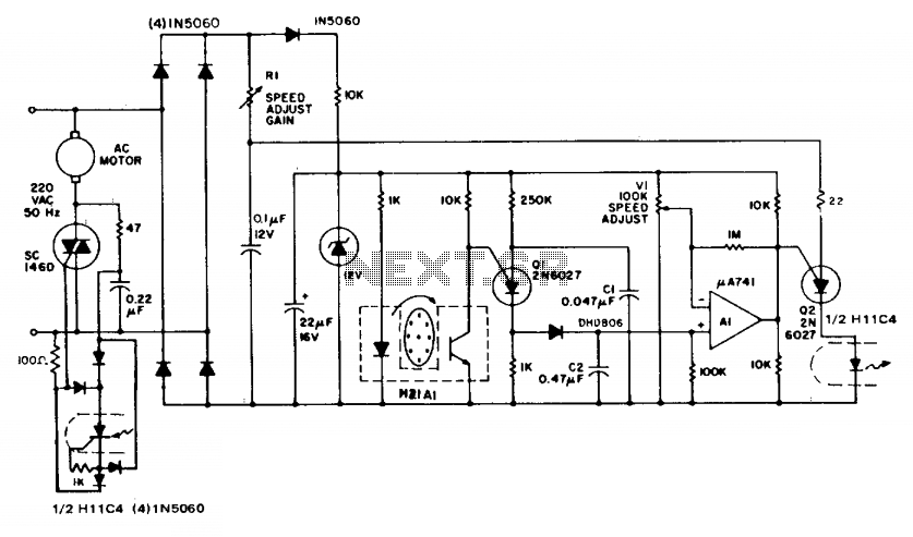
The described circuit employs a feedback mechanism to regulate the speed of an AC induction motor effectively. The key components involved include the apertured disc, which serves as a rotational speed detector, and the interrupter module that generates a light beam. As the motor rotates, the disc interrupts the beam, enabling the detection of the motor's speed through the discharge of capacitor C1. The programmable unijunction transistor (Q1) plays a crucial role in this process by controlling the discharge of C1 into the larger capacitor C2, which accumulates charge proportional to the motor's speed.
The operational amplifier (A1) is configured to compare the voltage on C2, which reflects the motor speed, against a reference voltage (V1). This comparison is essential for determining whether the motor speed is above or below the desired setpoint. The output from A1 translates this comparison into a DC control signal that modulates the second programmable unijunction transistor (Q2). This transistor is synchronized with the AC supply frequency, ensuring that the control signals are in phase with the power supply.
The triac, being the final control element in the circuit, receives trigger pulses from Q2. The timing of these pulses is critical, as it dictates the phase angle at which the triac conducts. The phase angle is influenced by the speed control resistor (R1) and the actual speed detected by the system. By adjusting R1, the user can fine-tune the motor speed, allowing for precise control over the motor's operation.
Overall, this circuit provides an effective and cost-efficient solution for speed regulation in AC induction motors, eliminating the need for expensive tachometers while maintaining accuracy and responsiveness in speed control.The circuit illustrates feedback speed regulation of a standard ac induction motor, a function difficult to accomplish other than with a costly, generator type, precision tachometer. When the apertured disc attached to the motor shaft allows the light beam to cross the interrupter module, the programmable unijunction transistor, Ql, discharges capacitor, Cl, into the much larger storage capacitor, C2.
The voltage on C2 is a direct function of the rotational speed of the motor. Subsequently, this speed-related potential is compared against an adjustable reference voltage, VI, through the monolithic operational amplifier, Al, whose output, in turn, establishes a dc control input to the second P.U.T. (Q2). This latter device is synchronized to the ac supply frequency and furnishes trigger pulses in the conventional manner to the triac at a phase angle determined by the speed control, Rl, and by the actual speed of the motor. 🔗 External reference
Related Circuits
Here is a circuit diagram designed for DIY enthusiasts who aim to construct a dual fan controller utilizing an ATtiny45 microcontroller. The circuit activates the first fan when the temperature reaches a user-adjustable dial setting and engages a second...
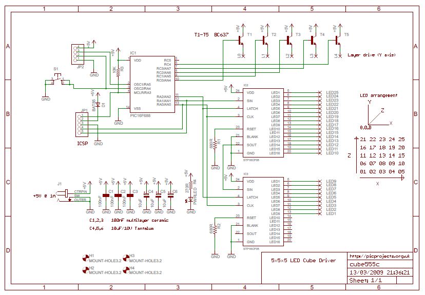
When viewing numerous videos on YouTube showcasing impressive LED cubes and intricate 3-D structures, it can be challenging to find explanations on how these creations are made. After searching online, an interesting project was discovered that utilizes a PIC...
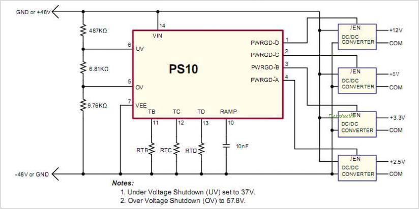
The Ultra Low Voltage Detectors PT7M6101 and PT7M6102 series are designed for overcurrent detection. They offer excellent circuit reliability and cost-effectiveness by eliminating the need for external components. These devices assert an OVRI signal when the voltage at the...
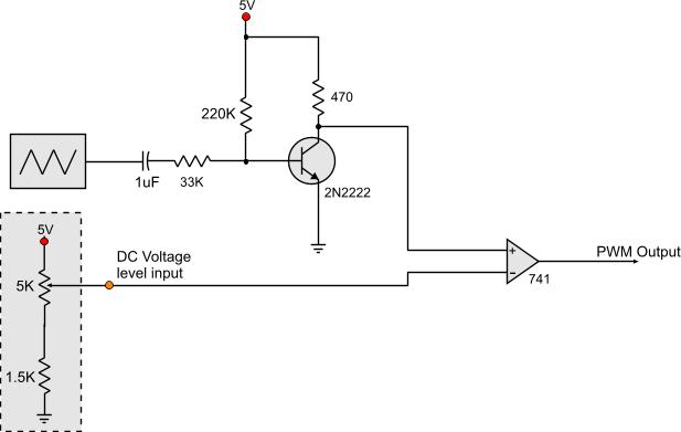
Circuits that generate PWM pulses typically translate a resistor value into a change in duty cycle. While this method is convenient, there are instances where a voltage-controlled PWM generator is required. Although microcontrollers can produce a variety of PWM...
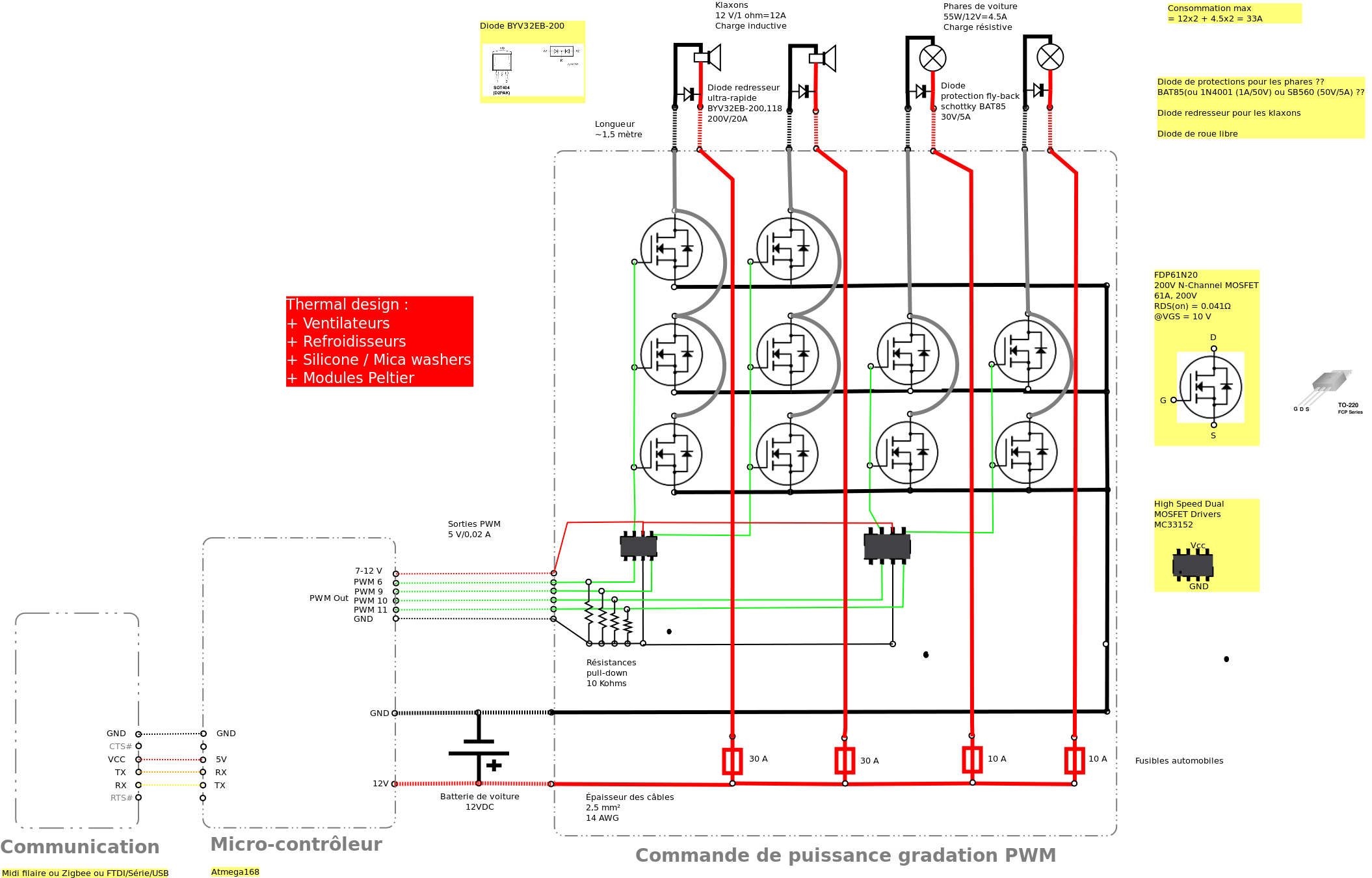
Past experiences were quite challenging due to the inductive nature of car horns, which require 12A of current, with peak demands reaching 20 to 30A. The current electronic system lacks reliability, given the high intensity. There is a need...
This circuit differs from similar circuits in view of its simplicity and a totally different concept of generating the control signals. Usually remote control circuits make use of infrared light to transmit control signals. Their use is thus limited...
Warning: include(partials/cookie-banner.php): Failed to open stream: Permission denied in /var/www/html/nextgr/view-circuit.php on line 713
Warning: include(): Failed opening 'partials/cookie-banner.php' for inclusion (include_path='.:/usr/share/php') in /var/www/html/nextgr/view-circuit.php on line 713