
Radio Remote Control using DTMF Circuit

This circuit design utilizes radio frequency (RF) technology to overcome the limitations imposed by infrared remote control systems, allowing for broader operational range and versatility. The core of the circuit is based on the generation and transmission of DTMF signals, which consist of two simultaneous audio frequencies. These frequencies are typically associated with the keypad tones of a telephone.
The transmitter section includes a DTMF encoder that converts the pressed key inputs into corresponding DTMF tones. These tones are then modulated onto a radio frequency carrier using a frequency modulation (FM) technique. The modulation process enables the information to be transmitted over a distance without the constraints of line-of-sight, typical of infrared systems.
At the receiver end, an RF receiver circuit is employed to capture the transmitted signals. The receiver is designed to demodulate the FM signals back into the original DTMF tones. This demodulation is crucial for restoring the control signals that can be interpreted by the subsequent control circuitry. The output from the receiver typically drives a speaker or can be interfaced with other electronic components to perform specific actions based on the received DTMF codes.
The overall architecture of this circuit offers significant advantages in terms of flexibility and range, making it suitable for various applications where remote control is needed without the limitations of traditional infrared systems. The use of DTMF signals not only simplifies the encoding process but also allows for multiple control commands to be sent through the same channel, enhancing the functionality of the remote control system.This circuit differs from similar circuits in view of its simplicity and a totally different concept of generating the control signals. Usually remote control circuits make use of infrared light to transmit control signals. Their use is thus limited to a very confined area and line-of-sight. However, this circuit makes use of radio frequency to transmit the control signals and hence it can be used for control from almost anywhere in the house.
Here we make use of DTMF (dual-tone multi frequency) signals (used in telephones to dial the digits) as the control codes. The DTMF tones are used for frequency modulation of the carrier. At the receiver unit, these frequency modulated signals are intercepted to obtain DTMF tones at the speaker terminals.
🔗 External reference
Related Circuits
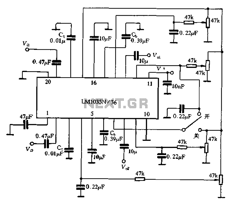
The circuit includes a loudness compensation control terminal at pin 7, which, when combined with the DC control voltage, forms a simple loudness compensation mechanism that enhances bass response. When the loudness control switch is in the OFF position,...
The following circuit illustrates a curtain control circuit diagram. This circuit is based on the 555 integrated circuit (IC). Features include a switch for manual control, the IC, and additional components. The curtain control circuit utilizes the 555 timer IC...
The function of the sound level display circuit is to enhance the appearance of an amplifier circuit or a radio player. It provides an impressive visual representation of audio levels. The sound level display circuit serves as a visual indicator...

The Pyro Propeller Clock POV schematic is relatively straightforward. It consists of three primary components: the power supply utilizing a 7805 voltage regulator, the LED output control managed by a PIC18F252 microcontroller and a 74LS373 latch, and the 'home'...
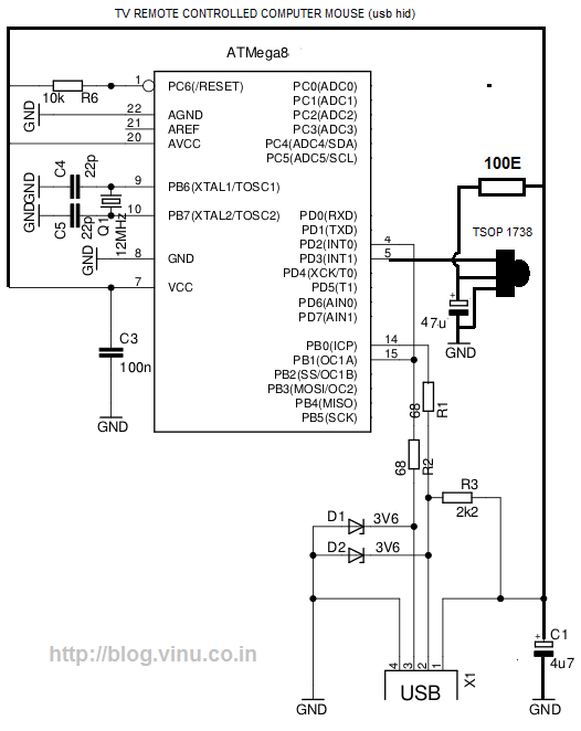
While lying in bed and watching movies on a laptop, the idea arose that having a remote control would simplify the tasks of pausing, playing, fast forwarding, rewinding, adjusting volume, and playing the next track without needing to approach...
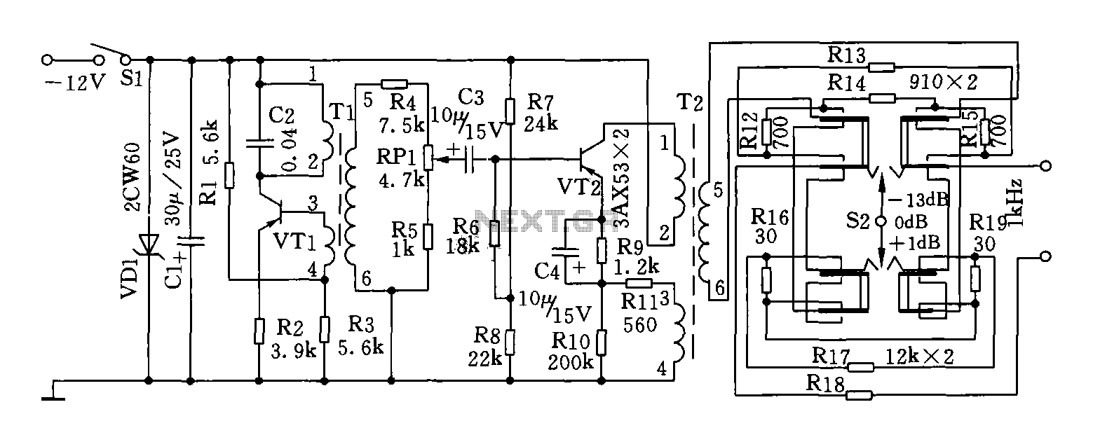
This circuit can generate a signal of 1 kHz and offers three output level options. It is suitable for testing communication equipment maintenance and barriers, providing a quick and accurate method to identify points of failure in televisions, stereos,...