
DIY Dual Fan Controller Project
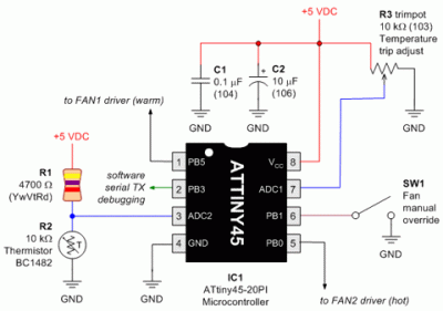
The dual fan controller circuit employs an ATtiny45 microcontroller as the central processing unit, which is programmed to monitor temperature readings from a thermistor or temperature sensor. The user can adjust the temperature threshold using a potentiometer, which provides an analog input to the microcontroller.
The circuit includes two output channels, each connected to a relay or transistor that controls the power to the fans. When the temperature detected by the sensor exceeds the threshold set by the potentiometer, the ATtiny45 sends a signal to activate the first fan. If the temperature rises above the threshold plus an additional 5 degrees Fahrenheit, the microcontroller triggers the second fan, ensuring effective cooling.
Power supply considerations should be taken into account, with appropriate voltage regulation to ensure stable operation of the ATtiny45 and the fans. A bypass capacitor is recommended near the microcontroller to filter any noise from the power supply. Furthermore, flyback diodes should be included across the relay coils to protect the microcontroller from voltage spikes when the relays are deactivated.
The circuit layout should be designed to minimize interference and ensure proper heat dissipation for the fans. Proper thermal management is crucial, especially in applications where high temperatures may be present. This dual fan controller circuit provides a flexible solution for managing cooling in various electronic projects, making it an excellent choice for DIY electronics enthusiasts.Here`s a nice little circuit diagram for all those hardcore DIYers if you are trying to build a dual fan controller using an ATtiny45 although I`d never use this thing, I`d rather use a CUBLOC. Over the course of a weekend, I cobbled together some leftover robot parts to create a simple dual-fan controller.
The board turns on the first fan when t he temperature reaches a user-adjustable dial setting, and it turns on a second fan if the temperature exceeds an additional 5 degrees Fahrenheit. With this method, only a single fan is used if the temperature can be kept under control with only one fan, but both fans will kick on if necessary.
🔗 External reference
Related Circuits
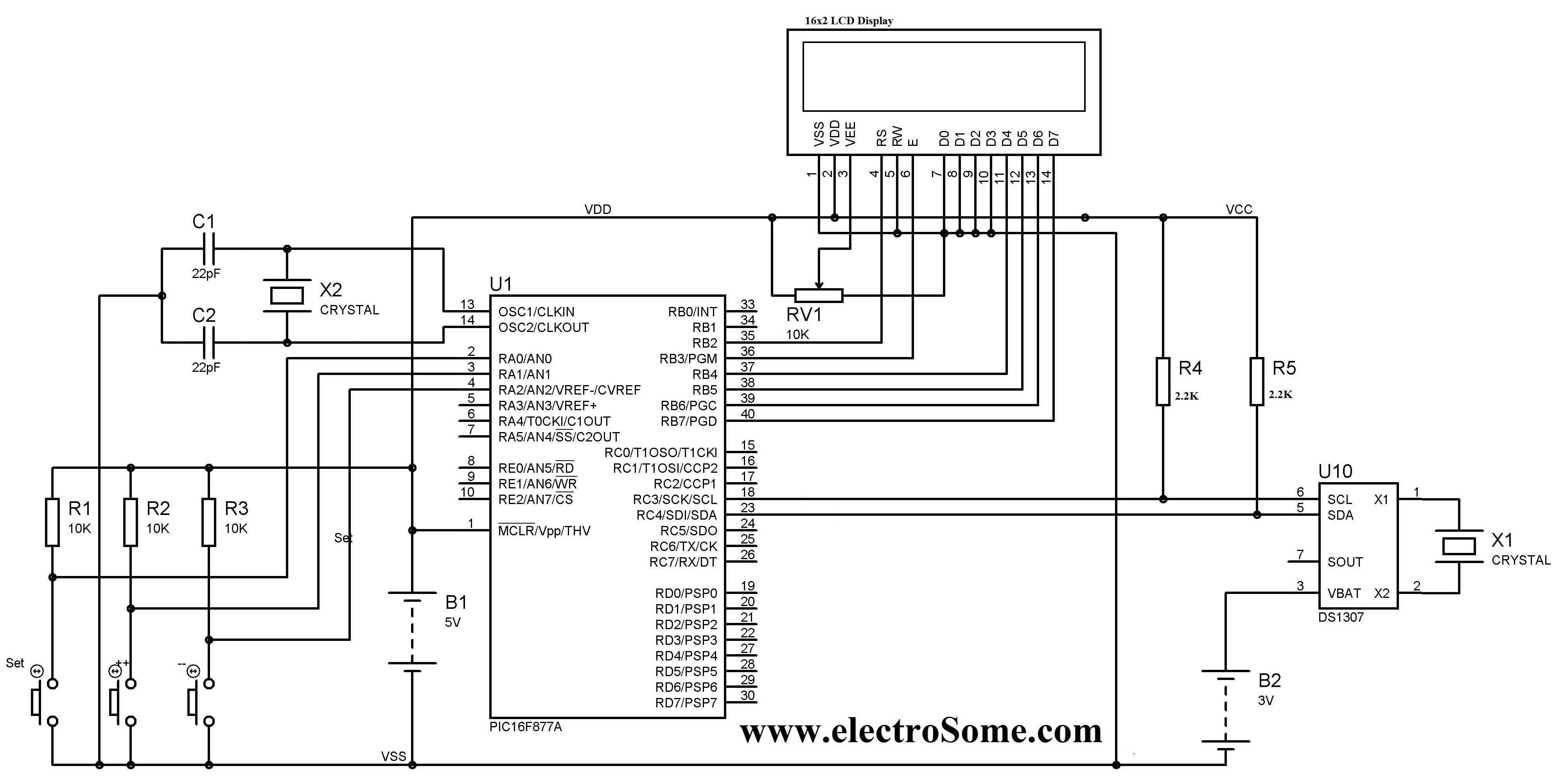
A digital clock can be constructed using a PIC microcontroller, DS1307 real-time clock (RTC), and a 16x2 LCD display. The DS1307 RTC operates in either 24-hour or 12-hour mode with an AM/PM indicator. It adjusts automatically for months with...
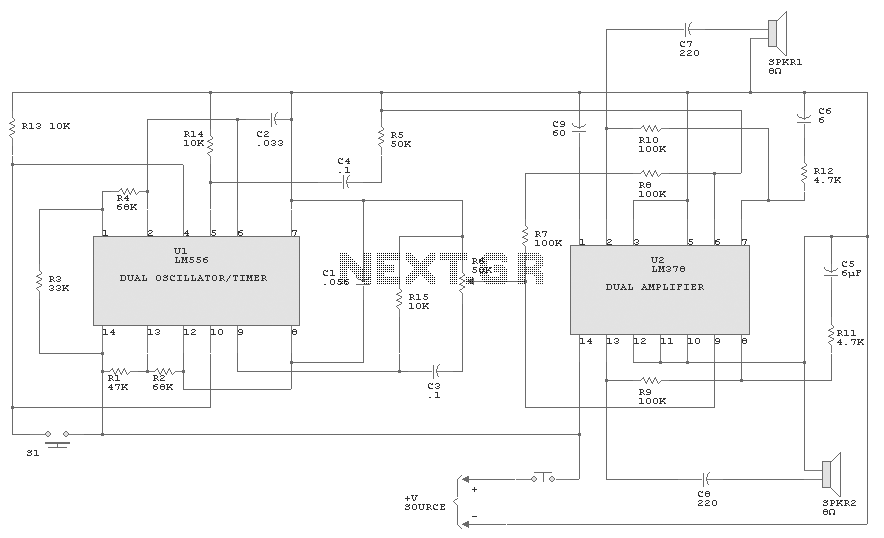
An LM556 dual oscillator/timer, U1, configured as a two-tone oscillator drives U2, a dual 4-watt amplifier. One of the oscillators, pins 1 to 6, contained in U1 produces the upper frequency signal of about 200 Hz, while the second...
The following circuit illustrates an Electric Car Audio Project. Features include a Rockford Fosgate Punch 4080DSM amplifier, which operates in a bridged 2-channel configuration at 4 ohms for component speakers. The Electric Car Audio Project utilizes the Rockford Fosgate Punch...
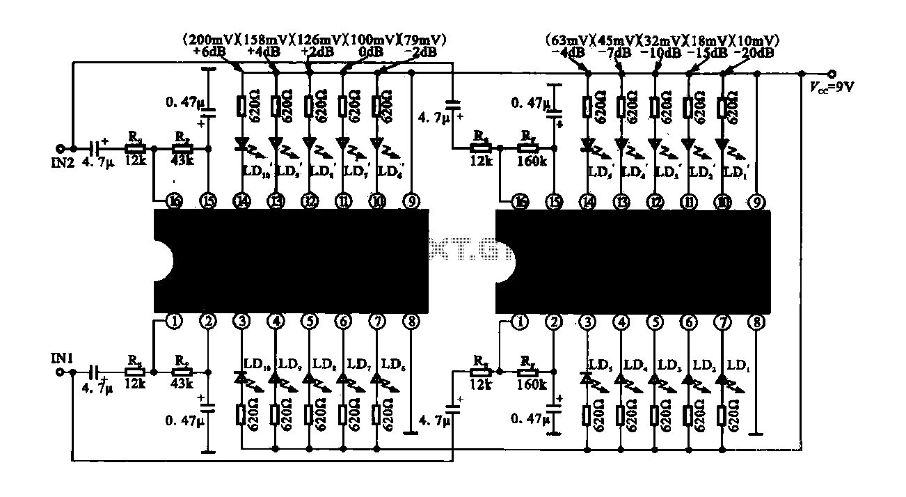
The circuit consists of dual drive integrated circuits (ICs) utilized in a 10 LED level meter configuration. The schematic features two TLM8101 driver ICs, which can be employed as alternatives. The 10 LED level meter circuit is designed to provide...
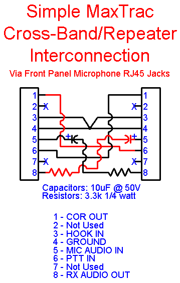
This article outlines a reliable, straightforward, and universal method for interfacing Motorola mobile radios from the MaxTrac, Radius, and GM300 series with common repeater controllers. The information provided is also relevant for radio interfaces used in IRLP or EchoLink...
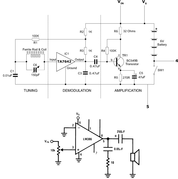
This functioning radio was built for an electronics module. The specified design was modified to include batteries, a switch, and a speaker instead of headphones. An additional amplifier circuit was required to power the speaker driver. Although not necessary,...
Warning: include(partials/cookie-banner.php): Failed to open stream: Permission denied in /var/www/html/nextgr/view-circuit.php on line 713
Warning: include(): Failed opening 'partials/cookie-banner.php' for inclusion (include_path='.:/usr/share/php') in /var/www/html/nextgr/view-circuit.php on line 713