
ac POWER MONITOR
The circuit operates by monitoring the AC power line voltage and providing visual feedback through the LED indicators. The voltmeter and neon lamp serve as primary indicators of the AC voltage level, providing a user-friendly interface for monitoring power conditions. The inclusion of the fuse and MOV is critical for the protection of the circuit against potential overvoltage conditions that can arise from transients or surges in the AC line.
The rectification of the AC voltage is achieved through the use of four 1N4004 diodes arranged in a full-wave rectifier configuration. This allows for the conversion of the AC voltage into a series of negative-going pulses, which are essential for the operation of the missing pulse detection circuit. The variable resistor F1 plays a crucial role in scaling the amplitude of these pulses to a level suitable for input to the missing pulse detector.
The missing pulse detector, which consists of Q1 (a transistor), IC1 (an integrated circuit), and additional components, continuously monitors the amplitude of the incoming pulses. The threshold value set by R1 determines the sensitivity of the circuit; if the pulse amplitude remains above this threshold, IC1 will keep its output high. The timing mechanism introduced by R2 and the capacitor ensures that the circuit can differentiate between momentary drops in pulse amplitude and sustained outages. This is particularly important in applications where brief interruptions may occur but do not warrant a dropout indication.
When the pulse amplitude falls below the threshold, IC1 times out, leading to a low output state that activates LED1 to indicate a dropout condition. The triggering of IC2, configured as a set-reset flip-flop, results in the activation of LED2, providing a secondary visual cue that a dropout has occurred. The manual reset feature allows for user intervention to reset the LED2 indicator once the power has stabilized.
The circuit’s power supply, a 9-V battery, ensures portability and ease of use, while the choice of a plastic or grounded metal case provides necessary physical protection and reduces the risk of electrical shock. Given the lack of isolation between the AC line and the monitor, it is imperative to handle the circuit with care during testing or troubleshooting to prevent electrical hazards.The 0-to 130-V voltmeter and neon "AC PWR" lamp provide an average indication of the ac power. The fuse and metal oxide varistor(MOV)protect the monitor against overvoltage spikes. Four 1N4004 diodes rectify the ac voltage, generating negative-going pulses twice per cycle(every 8. 33 ms for 60-Hz power). Variable-resistor F1 supplies a reduced ampl itude sample of these pulses to a missing pulse detector consisting of Q1, IC1, and associated circuitry. As long as the pulse amplitude exceeds the threshold value set by RI, IC1 continually triggers, keeping its output high.
When the pulse amplitude drGps below the threshold value, IC1 times out with a time constant set by variable resistor R2 and the 0. 47- F capacitor. R2 is calibrated to read the number of cycles required for a dropout indication. It can be set between 1 cycle(about 17 ms)and 30 cycles(0. 5 second). When IC1 times out, its output goes low. This turns on LED1. The low output also triggers IC2, which is configured as a set-reset flip-flop. This turns on LED2. When the voltage returns to normal, IC1 again starts triggering and its output returns high, turning off LED1.
LED2, however, remains on until the manual reset button is pressed. The circuit is powered by a 9-V battery and is assembled in a plastic or grounded metal case. No-tice that thqre`s no isolation between the ac power line and the monitor circuitry. Be careful to avoid electrical shock when testing the circuitry. 🔗 External reference
Related Circuits
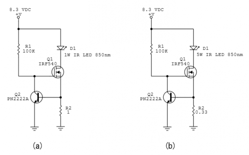
A constant-current power LED driver circuit is depicted in the schematic. Q1 is activated by R1 and functions as a variable resistor. Q2 serves as an “over-current” switch, while R2 establishes the maximum current. For the power LEDs utilized,...
This circuit allows appliances to remain connected to an inverter. While it does not influence weather conditions, it ensures that batteries are safely charged even during periods of generation shortfall. This device is referred to as the Grid Charger...

Note for bridge configuration: 1. Install jumpers JU2 and JU4. 2. Remove J1. 3. Remove RIO. 4. Replace R13 with a jumper wire. 5. Replace R15 with a 4.53 kΩ, 1% resistor. 6. Replace R14 with a 13 kΩ,...
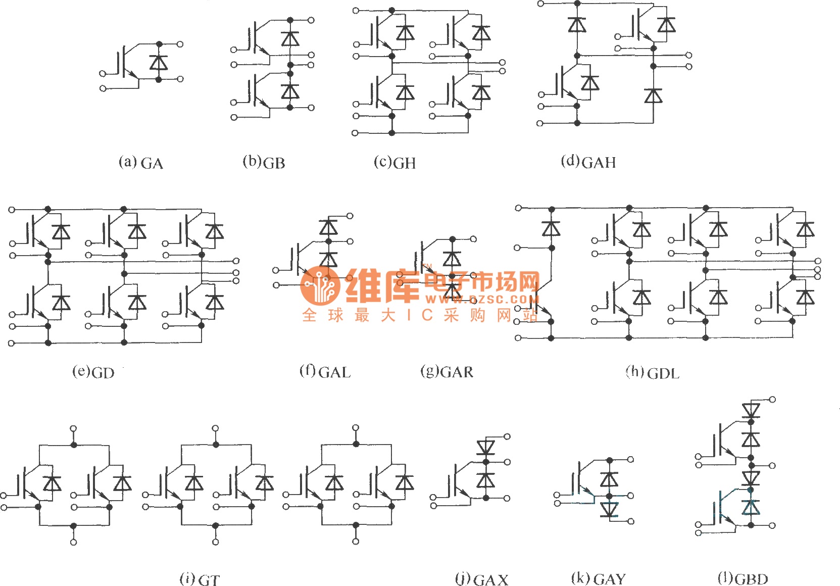
This document describes various electronic modules, including: (a) a single switch module; (b) a two-unit half bridge module; (c) an H bridge (single-phase bridge) module; (d) an asymmetrical H bridge module; (e) a three-phase bridge (six-unit or inverter bridge)...
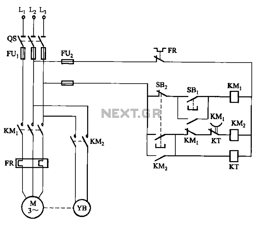
The circuit illustrated in Figure 3-123 operates as follows: When the stop button SBz is pressed, contact KMi releases, cutting off power to the motor. Simultaneously, KMz is activated, engaging the electromagnetic brake YB to hold the motor in...
The LM317T power supply circuit is a straightforward and enduring design that consists of a minimal number of components. It provides a stable, regulated, adjustable, or variable output. The LM317T is a versatile linear voltage regulator that can output a...