
High-Power Car Audio Amplifier
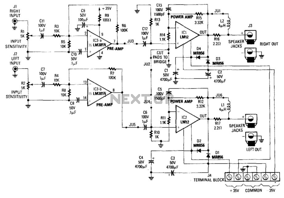
The circuit described pertains to a stereo amplifier with a bridge configuration. The setup requires specific modifications to optimize performance and ensure proper functionality. The installation of jumpers JU2 and JU4 is necessary to enable the bridge mode, which enhances the amplifier's power output capabilities. The removal of J1 and RIO is a crucial step in configuring the circuit for bridge operation.
Resistor modifications include replacing R13 with a jumper wire, which effectively bypasses that component, and substituting R15 with a 4.53 kΩ, 1% tolerance resistor. Additionally, R14 should be replaced with a 13 kΩ, 1% tolerance resistor, ensuring precise resistance values are maintained for stability and performance. The instruction to cut the foil between the pads from RH and ground is essential for isolating the circuit paths, preventing unintended connections that could lead to performance degradation.
The input configuration transforms into the left channel input, which is critical for stereo sound separation. Outputs from both the left and right channels are specified, allowing for a balanced audio performance. This amplifier is capable of delivering 60 W RMS into an 8-ohm load and 100 W RMS into a 4-ohm load, making it suitable for various audio applications.
The LM12C1 operational amplifier requires a line level input of approximately 300 mV for optimal performance. For full power output, a dual polarity supply of ±35 V is necessary. This power supply can be obtained using a DC-DC converter, which can efficiently convert available voltage levels to meet the amplifier's requirements. Overall, this configuration and the specified components ensure robust audio amplification suited for high-fidelity applications. NOTE: FOR BRIDGE CONFIGURATION: t install jumpers ju2 and ju4 2.remove j 1)3 3.remove rio 4replace r13 with jumper wire 5replace ri5 with 4.53k ohm 1% 6. replace r14 with 1 13k ohm 1% 7 cut foil between pads from rh and ground 8.input becomes left channel input 9.take ( output from left output 10 takf output from right output This stereo amp will supply 60 W rms into 8 or 100 W rms into 4 . Notice that the LM12C1 line level (about 300 mV) into 5 . A ±35-V supply is required for full power output. Power can be obtained from a dc-dc converter. 🔗 External reference
Related Circuits
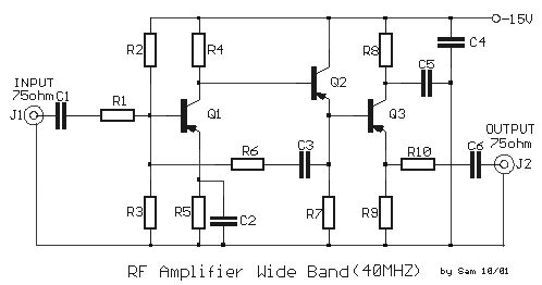
A wideband transmission or communication channel consists of a broader bandwidth than a single voice channel, utilizing a carrier wave of a specific modulated frequency. This allows for the transmission of more information than narrowband systems, but less than...
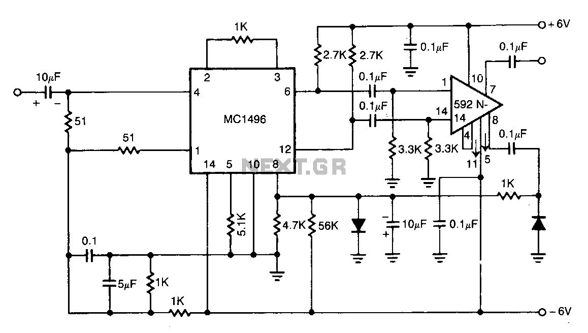
The NE592 is connected with the MC1496 balanced modulator to create an effective automatic gain control system. The signal is input to the MC1496 and then re-coupled to the NE592. Unbalancing the carrier input of the MC1496 allows the...
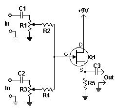
A compact and straightforward audio mixer utilizing a limited number of components centered around a FET transistor (2N3819). This audio mixer circuit is designed to combine multiple audio signals into a single output while maintaining signal integrity and minimizing distortion....
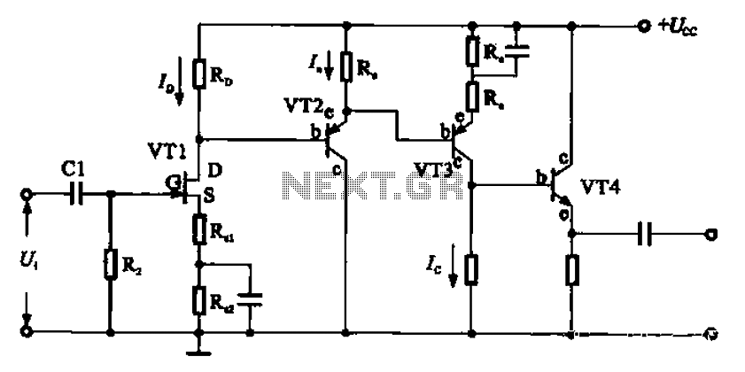
A combination of a common-source grounded emitter amplifier and a common emitter amplifier. The input impedance of the common emitter amplifier is in the range of 1.03 fl. Directly connecting the FET drive can be challenging; however, utilizing an...
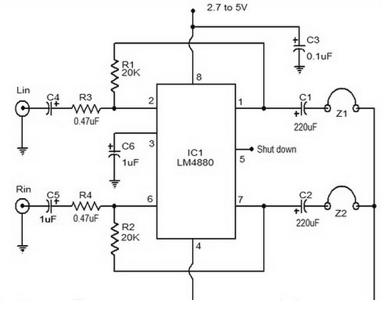
The LM4880 is a dual audio HiFi amplifier integrated circuit from National Semiconductor. This headphone amplifier circuit is specifically designed to produce high-quality audio output with a minimal number of components. The LM4880 integrated circuit is capable of delivering...
This amplifier is suitable for telephone applications or situations where a straightforward speech amplifier is necessary. The frequency response can be adjusted by changing the values of capacitors C2 and C4, and by adding a capacitor across resistor R4...