
Grid Powered Battery Charger
The Grid Charger Voltage Switch circuit integrates several key components to achieve its functionality. The PIC microcontroller serves as the brain of the operation, continuously monitoring the battery voltage through its analog-to-digital converter (ADC) capabilities. The adjustable low and high voltage set points can be configured via potentiometers connected to the microcontroller's input pins, allowing for flexibility based on the specific battery chemistry and system requirements.
The solid-state relay (SSR) is a critical component, chosen for its ability to handle high currents without the wear and tear associated with mechanical relays. It is essential to select an SSR with a current rating that exceeds the maximum expected load of the battery charger to ensure reliable operation. The control circuit for the SSR is straightforward, relying on a GPIO pin from the PIC microcontroller to switch the SSR on or off based on the monitored battery voltage.
The circuit design must also consider safety features, such as fuses or circuit breakers, to protect against overcurrent conditions. Additionally, proper heat dissipation strategies should be implemented for the SSR, especially if the charger operates at high currents for extended periods.
When constructing the circuit, careful attention should be paid to the layout on the breadboard or printed circuit board to minimize noise and interference, which can affect the microcontroller's performance. Proper decoupling capacitors should be placed near the power supply pins of the PIC microcontroller to ensure stable operation.
Finally, it is advisable to include LED indicators on the circuit to provide visual feedback on the status of the relay and battery voltage levels. This can aid in troubleshooting and ensure that the system operates as intended. By following these guidelines and considerations, the Grid Charger Voltage Switch can be effectively implemented to enhance the reliability and functionality of alternative energy systems.This circuit lets you keep the appliances plugged into your inverter. It won`t make the wind blow or the clouds go away, but it will keep your batteries safely charged even if you have a generation shortfall. I call it the Grid Charger Voltage Switch. The circuit utilizes a PIC microcontroller to monitor battery voltage and control a solid state relay, turning
it ON for a time period when battery voltage falls below an adjustable low voltage set point and OFF if it exceeds an adjustable high voltage set point. The circuit is extremely useful in alternative energy applications such as wind or solar, which experience long periods of calm or clouds when no power is generated to feed the battery array.
The switch works in tandem with your charge controller. You charge your batteries using your wind or solar generation capacity just like you always do, but if the batteries get low because your wind or solar stops, this device will automatically turn on a grid powered battery charger to protect the batteries from chronic undercharging. It will permit you to run continual loads even when the sun doesn`t shine or the wind doesn`t blow. I like to think of this switch as creating a sort of reverse grid-tie arrangement. The alternative energy system is connected to the grid, but instead of sending excess power out onto the grid, this arrangement uses grid power when it is needed to meet electric demand and keep the batteries charged when conditions are not good for energy production.
Unlike a true grid-tie, this system will not make your electric meter run backwards, but you don`t need the expensive equipment and your electric power will not stop when the public utility grid goes down. Build the circuit on a breadboard, PIC prototype board, or printed circuit board. You will also need to program the PIC 16F676 chip with the program downloaded from the link on the next page.
If you purchase a circuit board or kit on the last page, you will find more detailed assembly instructions in the assembly guide link at left. The parts list gives all necessary components. You will need to size the battery charger according to the size of your battery bank. Likewise, the solid state relay must be able to handle the current draw of the charger you select. Minimum control voltage of the relay is 3vdc. Connect the relay in series with the hot leg of a 120vac line such that when the relay is turned ON, a connection is made between a 120 volt wall outlet and your battery charger.
Connect wires between the battery inputs on the board and the battery bank`s positive and negative and negative terminals. 🔗 External reference
Related Circuits
The circuit diagram presented illustrates an IC-controlled emergency light with a charger, functioning as a 12V to 220V AC inverter circuit. This emergency light circuit is designed to automatically activate in the event of a mains failure, while also...
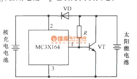
This is a simple NiCd battery charger powered by solar cells. A solar cell panel or an array of solar cells can charge a battery at more than 80% efficiency, provided the available voltage exceeds the fully charged battery...
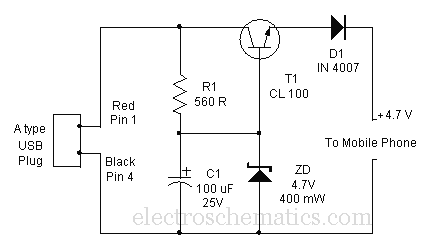
Comprehensive information about a USB cellphone charger circuit is available for learning and downloading online. The USB cellphone charger circuit is designed to convert AC mains voltage into a stable DC voltage suitable for charging mobile devices. This circuit typically...
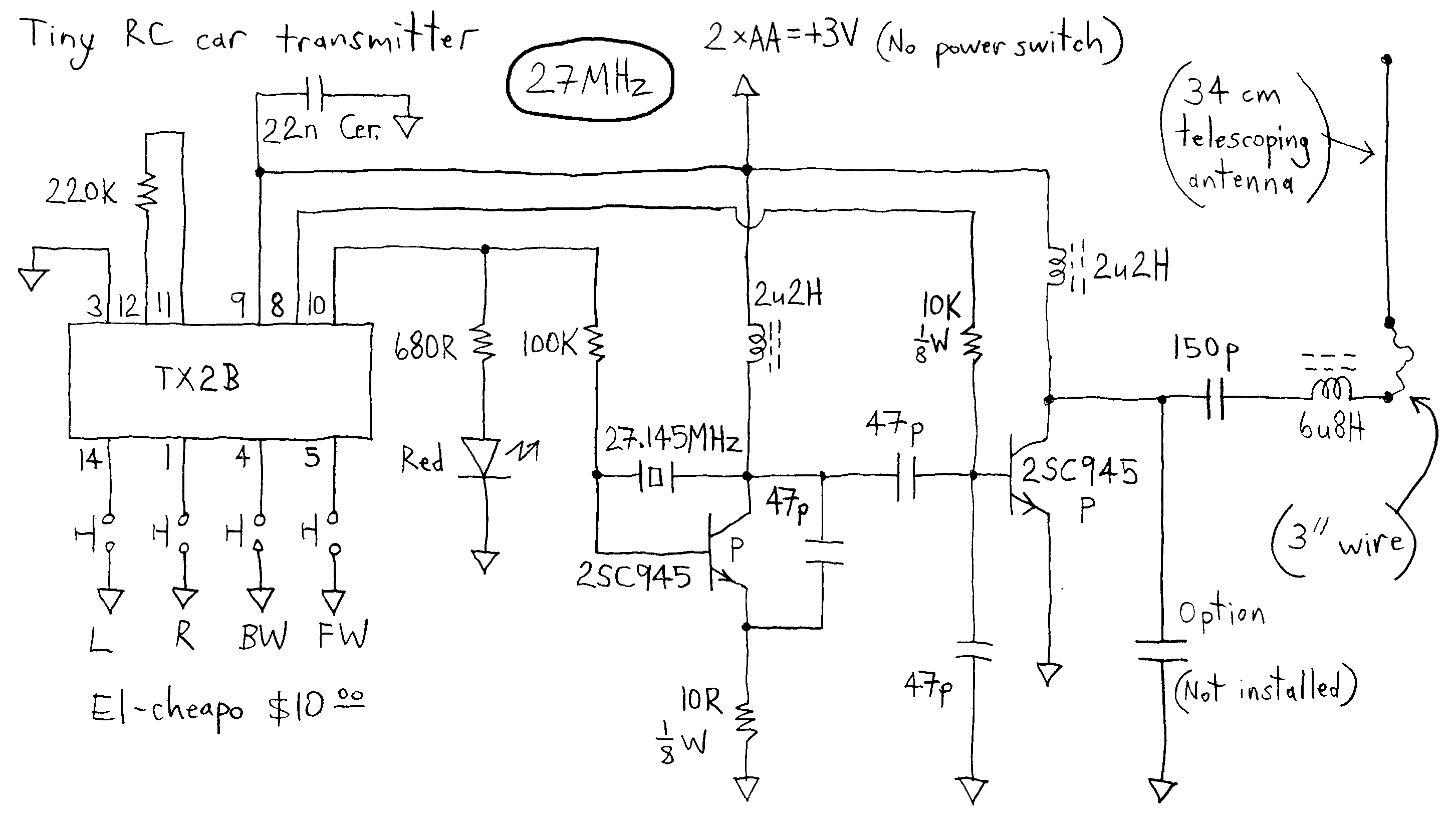
The transmitter runs on only 3V whereas most others run on more voltage. This dirt cheap item uses non-adjustable inductors so it is not possible to tweak for higher output. The common TX2B chip is manufactured by HIGHLAND (SHENZHEN)...
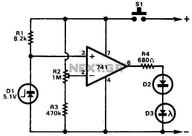
A 741 operational amplifier is utilized as a voltage comparator. The non-inverting input is connected to a zener reference source, providing a reference voltage of 5V. Resistor R2 is calibrated so that the voltage at the inverting input is...
The following circuit illustrates a current-limited solar battery charger circuit diagram. This lead-acid or Ni-Cd battery charger circuit diagram utilizes solar energy to charge a 6-volt, 4.5 Ah rechargeable battery for various applications. It represents a straightforward solar battery...
Warning: include(partials/cookie-banner.php): Failed to open stream: Permission denied in /var/www/html/nextgr/view-circuit.php on line 713
Warning: include(): Failed opening 'partials/cookie-banner.php' for inclusion (include_path='.:/usr/share/php') in /var/www/html/nextgr/view-circuit.php on line 713