
Ac-To-Dc Converter

The circuit utilizes two diodes (D1 and D2) configured in an inverse-parallel arrangement to efficiently rectify the AC voltage. When the AC voltage is applied, each diode conducts during alternate half-cycles, allowing the circuit to maintain a steady output voltage of approximately 1.4 Vpp, which is crucial for powering the primary coil of transformer T1. The transformer serves to step up the voltage for the secondary side, providing an output of around 11 Vpp, suitable for various applications including powering solid-state circuits.
The selected lamp (LMP-1) is connected to the AC input lines (L1 and L2) and operates within a voltage range of 120 V, drawing power between 5 to 25 W. This configuration ensures that as the lamp operates, it also maintains a stable voltage across the diodes, which in turn regulates the voltage supplied to T1. The transformer T1 can be chosen based on the specific requirements of the application, whether it be for radio output or other low-power electronic devices. The overall design ensures that the system remains efficient and reliable, with minimal variation in output voltage due to the inherent characteristics of the diodes and transformer. By coupling two back-to-back diodes in series with an ac power circuit, a voltage of about 1.4 Vpp can be obtained. This voltage is useful for exciting the primary coil of a small transformer. The voltage induced in the secondary coil can then be rectified and used to power solid-state control circuits. The forward-voltage drop of the diodes is inherently constant and stable over a wide range of ac-circuit power variations.
The resulting voltage developed across the transformer windings is also free from variation that might be caused by changes in the circuit"s current or voltage. In the circuit, a lamp (LMP-1) is connected to the primary ac input line (Ll and L2) through a pair of inverse-parallel-connected power diodes (Dl and D2).
As power flows to the lamp, a drop of about 0.7 V is alternatively developed across each of the diodes. This voltage feeds the primary of a small transformer (Tl). T1 can be a small 8- to 500- transistor radio output, etc. This will deliver about 11 Vpp across its secondary winding. LMP1 can be a small 120-V lamp of 5 to 25 W, etc.
Related Circuits
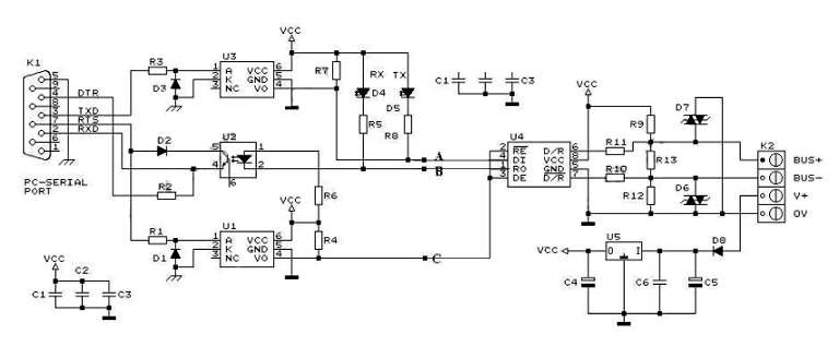
RS232 to RS485 Converter Circuit Schematic. RS232 to RS485 converters are primarily utilized in industrial and commercial settings. The RS232 to RS485 converter circuit is designed to facilitate communication between devices using different serial communication standards. RS232 is commonly found...
The TPS6420x controller is designed to operate with one to three series-connected cells or from a 3.3 V or 5 V supply obtained from a USB port. The TPS6420x is a highly versatile power management controller that facilitates efficient voltage...
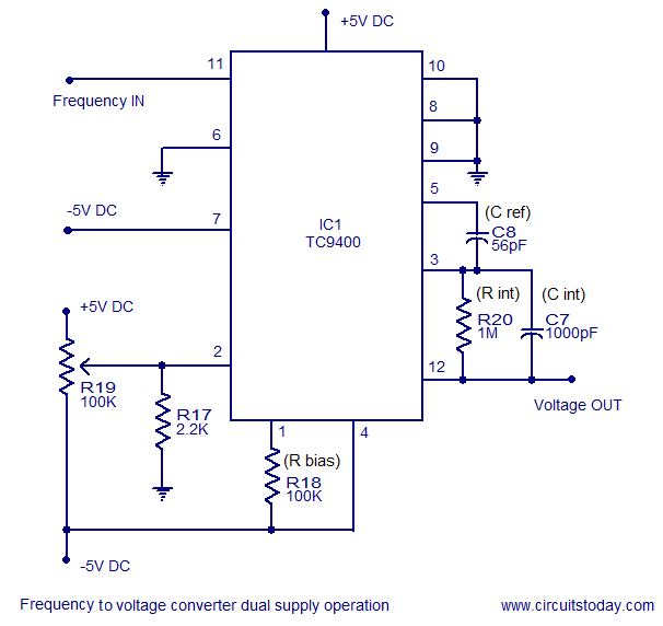
A simple frequency to voltage converter circuit designed around the TC9400 F to V / V to F converter IC. Dual and single supply versions are provided. The TC9400 is a versatile integrated circuit that converts frequency signals into corresponding...
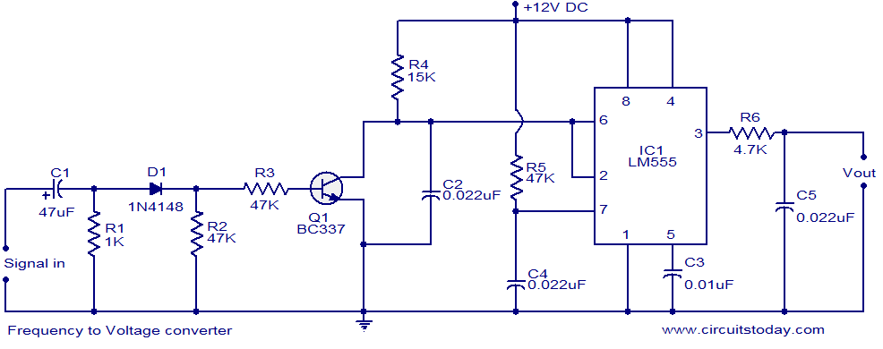
A simple frequency to voltage (F to V) converter circuit utilizing the LM555 Timer IC. This circuit has numerous applications in digital frequency meters, tachometers, and other related devices. The frequency to voltage (F to V) converter is a crucial...
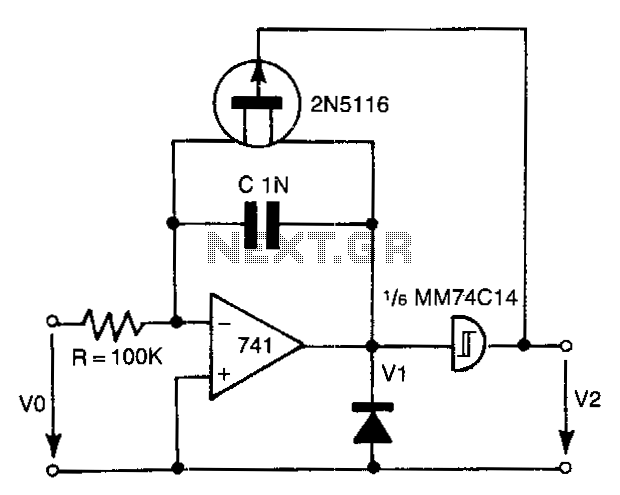
The 741 operational amplifier integrator signal is input into the Schmitt trigger of an inverter. When the signal reaches the positive-going threshold voltage, the inverter's output switches to zero. This output directly controls the FET switch. With a gate...
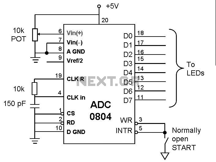
This post discusses the interfacing and operation of Analog-to-Digital Converters (ADCs). An ADC is a device that converts the analog signals from transducers into digital signals, enabling computers to process the data. ADCs are essential for obtaining meaningful results...