
ac Trouble with triac driven dimmer circuit
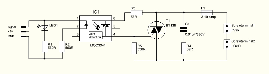
The described circuit involves a triac, which is a semiconductor device used for switching and controlling power. In this scenario, the triac is intended to control the brightness of a light source. The issue arises when the triac fails to turn on, leading to the light remaining off. When the gate of the triac is continuously supplied with voltage, it successfully activates the triac and the light reaches full brightness. This behavior suggests that the gate triggering mechanism is not functioning as intended under normal operation.
The resistor value of 56 Ohms before the triac gate may be a critical factor in the gate triggering process. If the resistor is too high, it could limit the current flowing into the gate, preventing the triac from turning on properly. It is essential to evaluate the gate current requirements of the specific triac being used and ensure that the resistor value allows sufficient current to trigger the device.
The mention of IC1 having zero edge detection indicates that it may be part of a circuit designed to detect zero crossings of an AC signal. Zero crossing detection is crucial for timing the triggering of the triac, as it minimizes electrical noise and reduces flickering in light dimming applications. The inquiry about sending a pulse to IC1 (pins 1 and 2) before the zero crossing suggests that the user is considering the timing of the control signal in relation to the AC waveform. Proper synchronization with the zero crossing is necessary to ensure that the triac is triggered at the correct moment.
The use of an optocoupler for zero crossing detection is a common practice in such circuits. An optocoupler can provide electrical isolation between the high voltage AC circuit and the low voltage control circuit, enhancing safety. The output of the optocoupler is then fed into the microcontroller, which processes the zero crossing information and generates the appropriate control signals for the triac.
In summary, the described circuit requires careful consideration of the resistor value at the triac gate, the timing of the control signals in relation to zero crossings, and the implementation of optocouplers for safe and effective operation. Adjustments to these components may resolve the issue of the triac not activating the light as intended.The triac should flip on and the light and it should be at nearly 100% brighness. However, this is not what`s happening. Itstead, the light doesn`t turn on at all. Can anyone explain why this might be If I change the gate to be always triggered (i. e. always voltage to the gate), the light turns on to 100% brightness as expected. Is it possible that the resistor sitting before the triac gate is too high (56 Ohms) I`m pretty new to this stuff, so you`ll have to bear with me. Not sure what you mean by "net", but since IC1 has zero edge detection, does that mean I need to send the pulse to the IC1 (pin 1 & 2) before the zero cross actually happens Matt Mar 26 `12 at 20:26 @Kortuk After thinking about your comments a bit more, I think you`re asking how I got the zero cross. I left that part of the circuit out of the question to avoid confusion as it didn`t really have anything to do with it.
I`m using another optocoupler to do that part and then feeding it`s output into the micro controller. Matt Mar 27 `12 at 2:44 @Kortuk The measurement was taken from a different part of the circuit (not shown in the schematic).
I`m using another opto coupler as a zero cross detector to know when to push the signal high. Matt Mar 27 `12 at 16:01 🔗 External reference
Related Circuits
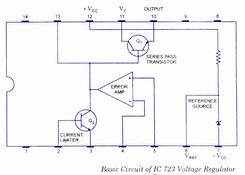
The working and block diagram of the IC 723 Voltage Regulator is provided along with the circuit diagram and applications. The IC 723 is a voltage regulator integrated circuit that is widely used for providing a stable output voltage. It...
The diagram illustrates a timed light control switch circuit designed for outdoor advertising light boxes, street lamps, and power control applications in Mexico. This time-saving switch circuit incorporates a manual door switch for controlling the lights, addressing the common...
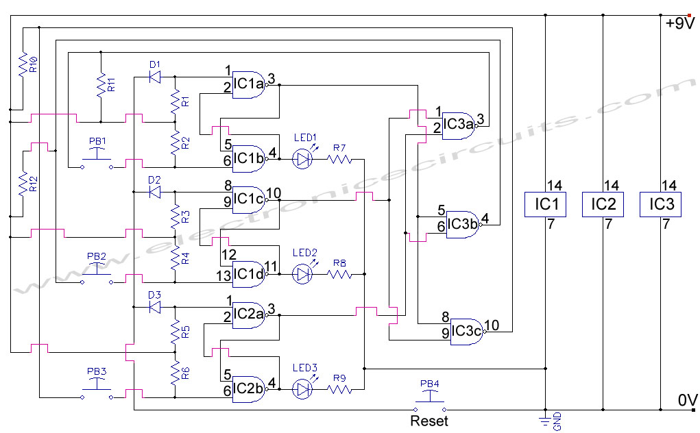
First Response Monitor, Input Selector, Game Circuit. This circuit is utilized for first response applications as it aids in monitoring various responses in games. The First Response Monitor circuit is designed to facilitate real-time monitoring and selection of input signals...

It is a self-oscillating voltage booster. It is relatively simple to build and it will allow you to use almost all the power in the battery, even when its voltage is low. The self-oscillating voltage booster is a circuit designed...
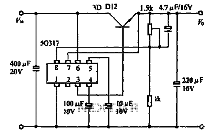
The 5G317 is an integrated voltage regulator circuit used in wiring applications for televisions. The maximum input voltage for the 5G317 should be less than 25V, while the output voltage ranges from 10V to 18V. The maximum output current,...

The Switchgate is a simple dual gate circuit based on a 556 timer configured in monostable mode, featuring a trigger input that activates two switches. The outputs of the monostables are also available individually. Recent research has led to...