
First Response Input Monitor Game Circuit
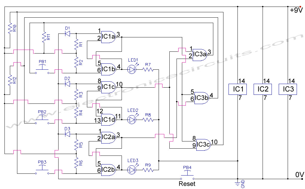
The First Response Monitor circuit is designed to facilitate real-time monitoring and selection of input signals in gaming and response applications. It typically consists of an input selector that routes signals from multiple sources to a single output, allowing for efficient management of data inputs from different game components or sensors.
The circuit can include a microcontroller or a dedicated input multiplexer, which serves as the core component for selecting the active input. The input selector can be configured to switch between various input sources, such as buttons, sensors, or other electronic devices, enabling the system to respond dynamically based on user interaction or environmental changes.
Signal conditioning elements may also be incorporated to ensure that the input signals are correctly formatted and amplified for processing. This might involve the use of operational amplifiers to enhance signal integrity or filters to eliminate noise.
The output of the circuit typically connects to a display or an output device, which visualizes the selected input or the monitored response. This can be particularly useful in gaming scenarios where quick feedback is essential for gameplay dynamics.
Overall, the First Response Monitor circuit is a versatile tool that enhances the interactivity and responsiveness of electronic systems, making it a valuable component in both gaming and monitoring applications.First Response Monitor, Input Selector, Game Circuit You can find first response using this circuit, because it helps many response monitor, games.. 🔗 External reference
Related Circuits
Most universal radio receivers have a very wide bandwidth that is not particularly suitable for radio amateurs. The better models with narrower bandwidth are almost a... Universal radio receivers are designed to operate over a broad frequency range, making them...
The industrial fuel oil furnace controller circuit consists of a power supply circuit, a testing and ignition control circuit, and a control implementation circuit, as illustrated in the accompanying diagram. The power supply circuit includes a step-down capacitor (C6),...
The circuit does not fail under slight variations, even if the input/output electric current characteristics are exceeded. Failure occurs only during a short circuit or extreme conditions at the output. The operation of the circuit is explained as follows:...
This circuit is beneficial for applications where a load must be activated from one location and deactivated from another. Multiple momentary normally open (N/O) switches or push buttons can be connected in parallel. The circuit described facilitates remote control of...
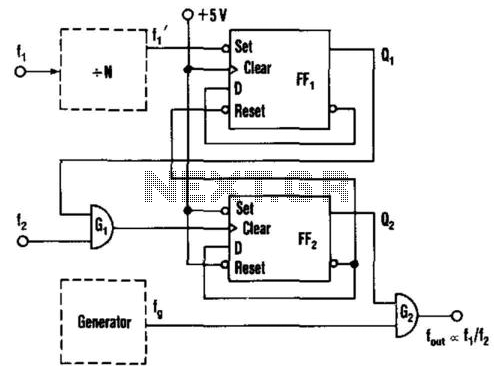
This circuit generates an output frequency that is linearly proportional to the ratio of two input frequencies. Each pulse of the bias frequency will open a switch for a period equal to half of the second input frequency, allowing...
The LM358 consists of two independent, high-gain operational amplifiers in a single package. An important feature of this integrated circuit (IC) is that it does not require separate power supplies for the operation of each comparator, accommodating a wide...