
make circuit diagram

The schematic also includes a precision LED bicycle charger comparator circuit and a brightness detection light control circuit. In the described setup, two resistors (R1 and R2) are configured to ensure that the total heat generated is equal, allowing for a calculated time ratio for circuit operation. For example, if resistors R1 and R2 are connected in series with a supply voltage (U), and both resistors have equal resistance, the power consumed can be calculated as U^2/2R. Conversely, when connected in parallel, the equivalent resistance becomes R/2, leading to a different power dissipation formula of U^2*2/R. Thus, for equal heat generation, the time ratio of operation can be derived as 4:1, depending on the configuration of the resistors.
Furthermore, the circuit employs a 555 timer configured to control the timing of LED illumination, ensuring that the lights remain on for a set duration (e.g., 10 minutes) before automatically turning off. This feature enhances the functionality of the photoelectric switch, which activates the LED lights when an object obstructs the light path. The design aims to provide an efficient and user-friendly solution for managing outdoor lighting in various applications, ensuring energy conservation and operational reliability.Diagram shows a timed light control switch circuit in Mexico, especially for outdoor advertising light boxes street lamps and power control, it is time saving switch circuit. Now with the door switch to manual control of lights and more, often forget to turn on the lights or turn off the lights because of inconvenience and energy waste.
If we can increase the light beam blocking alarm circuits. As shown, the photosensitive resistor R4 is irradiated, the resistance and, thus, one-way thyristor SCR transistor VT1 and are closing; lights automatically when light modulator circuit. As shown, this circuit is the intensity of light according to the outside world to automatically adjust the light brightness.
If the outside world, high brightness, light to dark, the light control switch. simple Shown is a simple light control switch. In some public places such as corridor, street lamps fitted with automatic light control switch, electronic metering system the camera is not. Cameras in the block, CdS photoresistor for electronic metering devices. Exposure to light from the plate in the photosensitive resistor CdS, moving the contents of secret. hot photosensitive Darlington transistor with self-locking function constitutes the light-emitting diode flash thyristor delay circuit schematic energy-saving light emitting diode matrix drive circuit automatically luminous photoresistor lamp light contro l timer switch circuit schematic novel precision LED bicycle charger comparator circuit schematic diagram of precision detectors brightness light control circuit As shown, the two resistors R1 = R2, the same supply voltage U, to make A and B two-circuit the total heat generated is equal, then the time required for a ratio of t: t B is () reward points: 0 | solution Time : 18:22 | Asked by: Lavender garden Connect A.
4: 1 B. 1: 4 C. 2: 1 D. 1: 2 must be explained in detail Oh! ! ! You help out! ! ! There will not be a problem, we must help each other it! ! ! Thank you! ! ! Image is: A: two resistors R1 and R2 in series, the power is U B: two resistors R1 and R2 in parallel, power is U you sorry, I really will not find pictures, but the image is a schematic generally mean! ! also the best answer, please forgive me The answer is A. A figure in, R1 and R2 in series and R1 = R2, equal to 2R resistor circuit associated to the heat, voltage U, so the electric power for the U * U/2R in B R1 and R2 in parallel graph, and R1 = R2, equivalent to a resistance R / 2 associated resistance to the circuit, when electric power for the U * U * 2 / R, so in order to produce as much heat, the time ratio of 4:1 help me answer 7 Time: 14:01 | to the TA for helpSuper thanks!
Thank you so much relevant content friends the resistance is the resistance of resistor R1 R2 Resistance 2 times. If R1 and R2 in series connected to the power voltage U, . 6 two electric heaters, the resistance R1 Timer is designed with a timing circuit 555, timing light to time to make LED light for 10 minutes, 10 minutes after the lights go out.
To reward points schematic ~ ~ ~: 0 | solution time : 18:44 | Asked by: gyz19880707 I designed the circuit in photoelectric switch, photoelectric switch when the object blocking the LED lights will light, and now I would like to add a function, a timer with 555 timer circuit design, timing light to time to make LED light for 10 minutes, hope to have a circuit diagram. LED lights are 12V, thank you I designed the circuit in photoelectric switch, photoelectric switch when the object blocking the LED lights will light, and now I would like to add a function of time with the design of a 555 timer circuit, the LED lights time to time to light for 10 minutes, the main films for light boxes, that is, when the film on the photoelectric switch above the LED lights recessed light, and took down the film after, with a 555 timer to design a timing circuit, the LED lights time to time to light for 10 mi
🔗 External reference
Related Circuits
The circuit diagram for a multiple output digital camera power supply using the MAX1802 is illustrated below. The MAX1802 chip features two buck converters and three boost converters. It accepts an input voltage range of 2.5 to 11V and...
This circuit is a low-frequency Wien bridge sinusoidal oscillator designed for the audio range, characterized by very low distortion, making it suitable for testing various audio equipment. The circuit has undergone thorough testing, and a printed circuit board (PCB)...
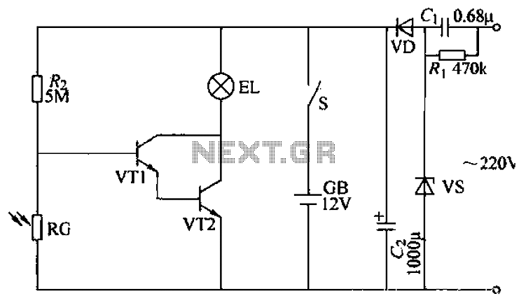
The power supply circuit features a step-down capacitor (C1), bleeder resistors (R), a Zener diode (VS), a full diode (VD), and a filter capacitor (G), along with switches and batteries (GB, SC). The light control circuit is composed of...
The circuit operates continuously, turning on and off. It utilizes the widely recognized NE555 timer IC, known for its versatility in various electronic applications. In this configuration, the IC is set up as an astable multivibrator. A 12-volt relay...
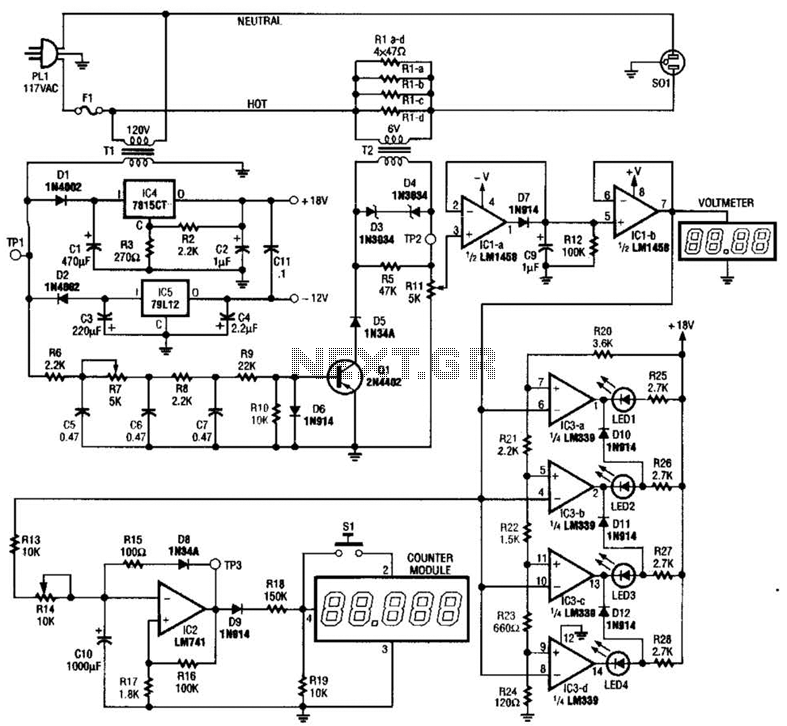
The ECM circuit comprises four sections, as illustrated in the block diagram. A power converter generates a voltage that correlates with the actual real power consumed by the load. This voltage supplies both a bar graph and a voltage-to-pulse...
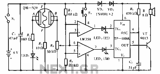
The QM-NJ9 is an alcohol sensor that detects the presence of alcohol by measuring the resistance values between points A and B. When alcohol is detected, the resistance decreases, leading to an increase in potential at point B. As...