
Access room people number counter circuit
The circuit operates based on the interruption of light beams emitted by the transmitters A and B, which are aimed at their respective photoresistors LDR1 and LDR2. When an object passes through the access channel, it obstructs the light path between the transmitter and receiver pair, resulting in a change in resistance of the photoresistor.
In practical terms, when light from source A strikes LDR1, it causes a decrease in its resistance, allowing current to flow through the circuit. This change can be detected by a microcontroller or a comparator circuit, which can trigger an output action, such as sounding an alarm or activating a gate mechanism. Similarly, when light from source B is interrupted, LDR2 experiences a change in resistance that can also be monitored.
The circuit can be designed to include additional components such as amplifiers to enhance the signal from the photoresistors, and logic gates to process the output signals more effectively. Power supply considerations should also be addressed to ensure that the light sources and the detection devices operate efficiently. Overall, this photoelectric detection system provides a reliable method for monitoring access channels in various applications, such as security systems or automated entry controls.Working principle: Two pairs of photoelectric detection devices are installed in the access channel. On one side the light source A (transmitter) and the photoresistor LDR1 (receiver) are installed in the entrance of the channel; on the other side, the light source B (transmitter) and the photoresistor LDR2 (receiver) are installed in the outlet of the chann.. 🔗 External reference
Related Circuits
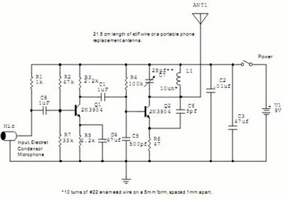
The following circuit illustrates a Wireless Car Alarm Circuit Schematic Diagram. Features include the ability to detect sounds within a 20-meter radius, a 1/16 wavelength antenna, and the capability to transmit radio signals up to 2 kilometers. Q1 serves...
The circuit described is a simple sound level meter, also known as a VU meter, which helps monitor sound levels to prevent hearing loss caused by loud music. It is a passive type of meter, requiring no separate power...
All sound effects are generated internally by the HT2884 integrated circuit (IC). The device operates on a 3-volt battery but is compatible with any voltage ranging from 2.5 to 5 volts. Switch S1 functions as the on/off switch. The...
VOX is a voice-activated switch commonly used with microphones as an alternative to traditional push-button switches. The VOX can be connected to various audio equipment featuring an external speaker for coupling. The activation threshold is adjusted using the volume...
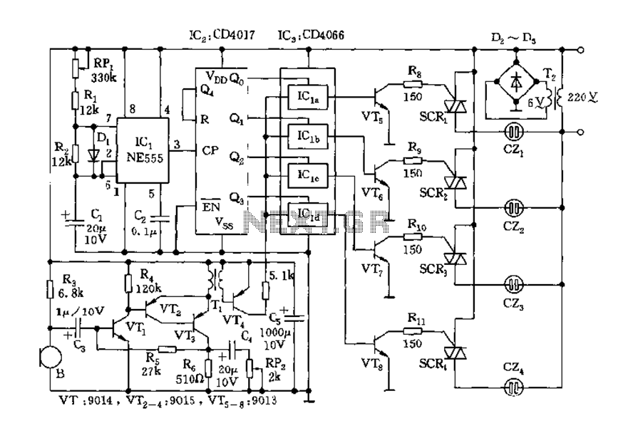
The circuit includes a controller that integrates an acoustic-electric conversion and amplification circuit, a clock pulse generator, a counting circuit, and a control circuit. It manages four accompanying music tracks and flashing lights. Microphones (MIC) convert sound into electrical...
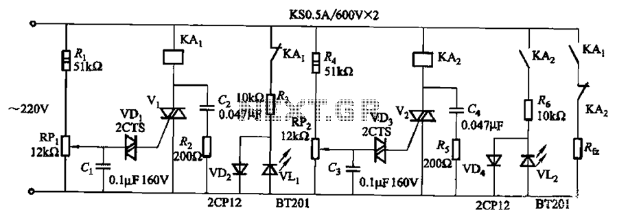
Bidirectional thyristor control. By adjusting potentiometers RPi and RPz, the lower and upper limit values can be changed. LEDs VLi and VL2 serve as indicators for low pressure and high pressure, respectively. The circuit utilizes a bidirectional thyristor to control...
Warning: include(partials/cookie-banner.php): Failed to open stream: Permission denied in /var/www/html/nextgr/view-circuit.php on line 713
Warning: include(): Failed opening 'partials/cookie-banner.php' for inclusion (include_path='.:/usr/share/php') in /var/www/html/nextgr/view-circuit.php on line 713