
A Noise Meter Circuit::: save ears PCB
The VU meter circuit is designed to visually represent audio signal levels through a series of LEDs. The circuit operates by connecting to the output terminals of an audio amplifier, where it derives its power from the audio signal itself. This passive design simplifies the setup, as no external power source is required. The primary function of the VU meter is to indicate sound levels, which is essential for preventing potential hearing damage from prolonged exposure to high volume levels.
In this circuit, seven LEDs are arranged to light up in sequence, corresponding to increasing levels of audio power delivered to an 8-ohm load. The first LED (D1) activates at low audio voltages, with subsequent LEDs (D2 through D7) illuminating as the volume increases. This visual feedback allows users to gauge the intensity of the audio output and adjust accordingly.
The LEDs are chosen for their low forward voltage and brightness at low current levels, making them suitable for this application. Each LED is controlled by a dedicated current source, which is implemented using field-effect transistors (FETs). These FETs are configured with resistors to limit the current to approximately 1 mA, ensuring that the LEDs do not exceed their rated current and become damaged. The actual current may vary slightly due to component tolerances, typically ranging from 0.65 mA to 0.98 mA in practical applications.
Zener diodes (D8 to D13) are integrated into the circuit to establish a threshold voltage for each LED, ensuring that they only illuminate when the input signal reaches a defined level. The Zener voltage is set to be approximately 3 volts lower than the voltage required for the corresponding power level, accounting for voltage drops across the circuit components.
To manage higher input voltages, the circuit employs transistors (T7 and T8) to amplify the signal and stabilize the LED supply voltage around 30 volts. This design choice ensures that the VU meter can handle signals from powerful amplifiers without damage. The circuit also includes a half-wave rectification stage using a diode (D14) to convert the AC signal from the loudspeaker into a usable DC signal for the LEDs.
Resistor R9 is strategically placed to limit the load on the amplifier and minimize distortion. Capacitor C1 plays a crucial role in determining the response time of the circuit, affecting how quickly the LEDs react to changes in signal levels. By adjusting the capacitance, the circuit can be tuned for faster response times, making it more sensitive to transient peaks in audio signals.
Overall, this VU meter circuit provides an effective and straightforward solution for monitoring audio levels, helping users protect their hearing while enjoying music. Its design balances simplicity, functionality, and safety, making it an excellent addition to any sound system.Circuit Hello HELLO! Are you deaf Do you have disco ears ` If people ask you this and you`re still well below 80, you may be suffering from hearing loss, which can come from (prolonged) listening to very loud music. You won`t notice how bad it is until it`s too late, and after that you won`t be able to hear your favorite music the way it real
ly is so an expensive sound system is no longer a sound investment. To avoid all this, use the i-trixx sound meter to save your ears (and your neighbor`s ears!). With just a handful of components, you can build a simple but effective sound level meter for your sound system. This sort of circuit is also called a VU meter. The abbreviation VU` stands for volume unit`, which is used to express the average value of a music signal over a short time.
The VU meter described here is what is called a passive` type. This means it does not need a separate power supply, since the power is provided by the input signal. This makes it easy to use: just connect it to the loudspeaker terminals (the polarity doesn`t matter) and you`re all set.
The more LEDs that light up while the music is playing, the more you should be asking yourself how well you are treating your ears (and your neighbours` ears). Of course, this isn`t an accurately calibrated meter. The circuit design is too simple (and too inexpensive) for that. However, you can have a non-disco type (or your neighbors) tell you when the music is really too loud, and the maximum number of LED lit up at that time can serve you as a good reference for the maximum tolerable sound level.
Although this is a passive VU meter, it contains active components in the form of two transistors and six FETs. Seven LEDs light up in steps to show how much power is being pumped into the loudspeaker. The steps correspond to the power levels shown in the schematic for a sine-wave signal into an 8-ohm load.
LED D1 lights up rst at low loudspeaker voltages. As the music power increases, the following LEDs (D2, D3, and so on) light up as well. The LEDs thus dance to the rhythm of the music (especially the bass notes). LEDs. They have a low forward voltage and are fairly bright at current levels as low as 1 mA. Connect the VU meter to the loudspeaker you want to monitor. If LED D2 never lights up (it remains dark even when LED D3 lights up), reverse the polarity of diode D8 (we have more to say about this later on). In addition, bear in mind that the sound from the speaker will have to be fairly loud before the LEDs will start lighting up.
If you want to know more about the technical details this VU meter, keep on reading. Each LED is driven by its own current source so it will not be overloaded with too much current when the input voltage increases. The current sources also ensure that thenal amplifier is not loaded any more than necessary. The current sources for LEDs D1 D6 are formed by FET circuits. A FET can be made to supply axed current by simply connecting a resistor to the source lead (resistors R1 R6 in this case).
With a resistance of 1 k ©, the current is theoretically limited to 1 mA. However, in practice FETs have a especially broad tolerance range. The actual current level with our prototype ranged from 0. 65 mA to 0. 98 mA. To ensure that each LED only lights up starting at a dened voltage, a Zener diode (D8 D13) is connected in series with each LED starting with D2. The Zener voltage must be approximately 3 V less than the voltage necessary for the indicated power level.
The 3-V offset is a consequence of the voltage losses resulting from the LED, the FET, the rectier, and the over voltage protection. The over voltage protection is combined with the current source for LED D7. One problem with using FETs as current sources is that the maximum rated drain source voltage of the types used here is only 30 V.
If you want to use the circuit with an especially powerful nal amplifier, a maximum input level of slightly more than 30 V is much too low. We thus decided to double the limit. This job is handled by T7 and T8. If the amplitude of the applied signal is less than 30 V, T8 buffers the rectied voltage on C1. This means that when only therst LED is lit, the additional voltage drop of the over voltage protection circuit is primarily determined by the base emitter voltage of T8.
The maximum worst-case voltage drop across R8 is 0. 7 V when all the LEDs are on, but it has increasingly less effect as the input voltage rises. R8 is necessary so the base voltage can be regulated. R7 istted in series with LED D7 and Zener diode D13, and the voltage drop across R7 is used to cause transistor T7 to conduct. This voltage may be around 0. 3 V at very low current levels, but with a current of a few mili-amperes it can be assumed to be 0. 6 V. Transistor T7 starts conducting if the input voltage rises above the threshold voltage of D7 and D13, and this reduces the voltage on the base of T8.
This negative feedback stabilizes the supply voltage for the LEDs at a level of around 30 V. With a value of 390 © for R7, the current through LED D7 will be slightly more than 1 mA. This has been done intentionally so D7 will be a bit brighter than the other LEDs when the signal level is above 30 V. When the voltage is higher than 30 V, the circuit draws additional current due to the voltage drop across R8.
The AC voltage on the loudspeaker terminals is half-wave recti ed by diode D14. This standard diode can handle 1 A at 400 V. The peak current level can be considerably higher, but don`t forget that the current still has to be provided by the nal amplier. Resistor R9 is included in series with the input to keep the additional load on the nal ampli er within safe bounds and limit the interference or distortion that may result from this load.
The peak current can never exceed 1. 5 A (the charging current of C1), even when the circuit is connected directly to an AC voltage with an amplitude of 60 V. C1 also determines how long the LEDs stay lit. This brings us to an important aspect of the circuit, which you may wish to experiment with in combination with the current through the LEDs.
An important consideration in the circuit design is to keep the load on the nal ampli er to a minimum. However, the combination of R9 and C1 causes an averaging of the complex music signal. The peak signal levels in the music are higher (or even much higher) than the average value. Tests made under actual conditions show that the applied peak power can easily be a factor of 2 to 4 greater than what is indicated by this VU meter.
This amounts to 240 W or more with an 8- © loudspeaker. You can reduce the value of C1 to make the circuit respond more quickly (and thus more accurately) to peak signal levels. Now a few comments on D8. You may receive a stabistor (for example, from the Philips BZV86 series or the like) for D8. Unlike a Zener diode, a stabistor must be connected in the forward-biased direction. A stabistor actually consists of a set of PN junctions in series (or ordinary forward-biased diodes).
Check this carefully: if D2 does not light up when D8 is tted as a normal Zener diode, then D8 quite likely a stabistor, so you should t it the other way round. 🔗 External reference
Related Circuits
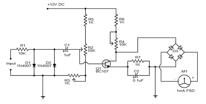
A simple tachometer schematic is presented. It utilizes a frequency converter circuit that transforms the input signal into a proportional current, which is then measured by a pointer device. The deflection of the milliammeter is proportional to the frequency...
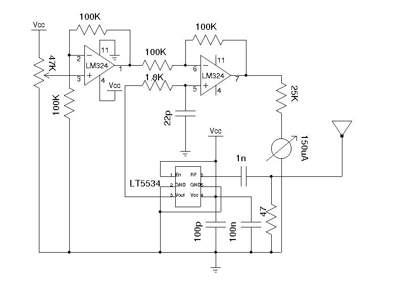
A field strength meter is highly beneficial when dealing with RF devices. It allows for the rapid diagnosis of transmitter circuit functionality and can detect RF signals present in the environment. The simplest form of a field strength meter...
Because it uses few parts, a printed circuit board is not necessary; components can simply be soldered to one another. However, a box is desirable for operating convenience. The case and aerial from a discarded toy walkie-talkie was used...
The AVO VCM 163 is a tube tester capable of measuring tube electrode currents, such as plate and screen currents, as well as mutual conductance simultaneously. It is the most advanced tube tester developed by AVO. The voltages applied...
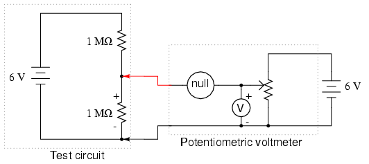
The potentiometer value is not critical; any value from 1 kΩ to 100 kΩ is acceptable. If the "precision potentiometer" described earlier in this chapter has been constructed, it is recommended for use in this experiment. The actual values...
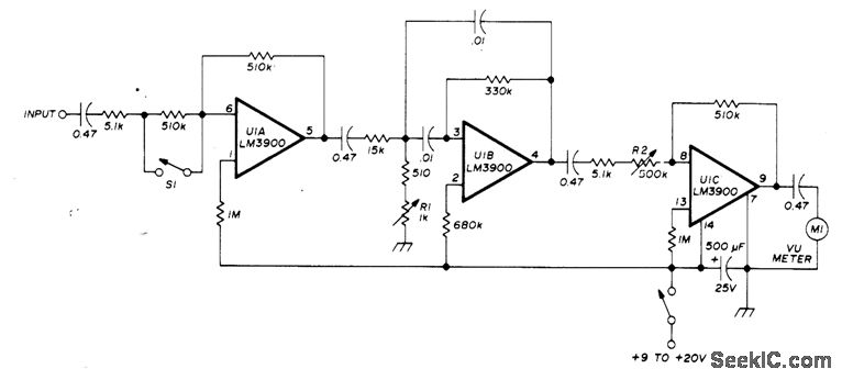
A simple and easily transportable VSWR meter is composed of a high-gain amplifier, a narrow-bandwidth selective amplifier tuned to 1000 Hz with a bandwidth of 100 Hz, and a variable-gain output amplifier that drives a low-cost VU meter. This...
Warning: include(partials/cookie-banner.php): Failed to open stream: Permission denied in /var/www/html/nextgr/view-circuit.php on line 713
Warning: include(): Failed opening 'partials/cookie-banner.php' for inclusion (include_path='.:/usr/share/php') in /var/www/html/nextgr/view-circuit.php on line 713