
Accu charger use a diac and triac Schematic Diagram
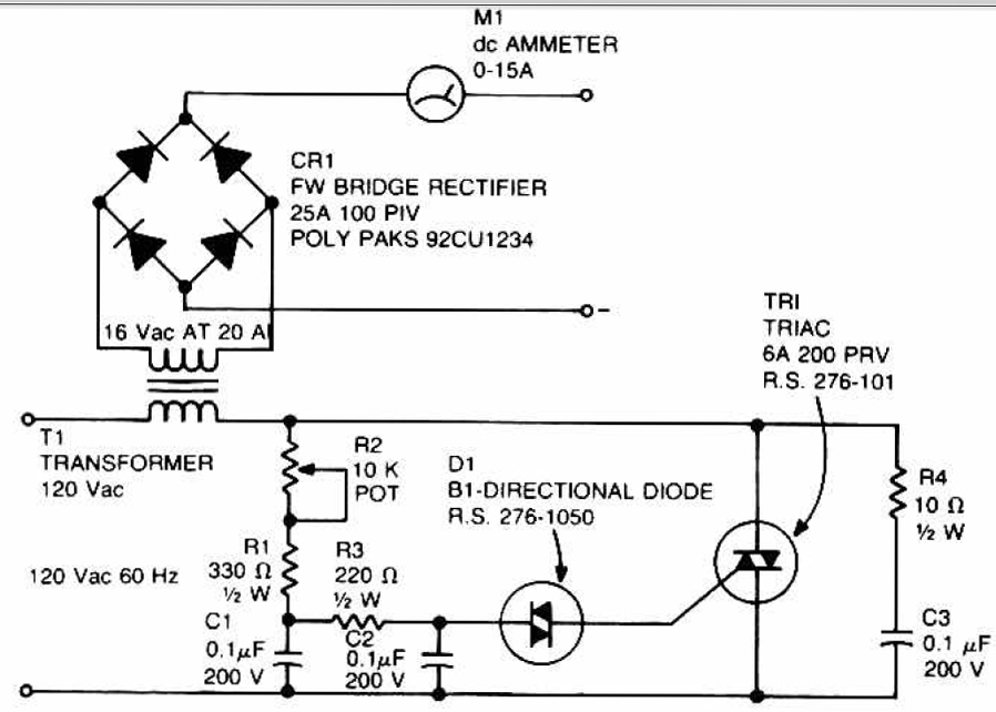
The described circuit serves as an efficient battery charger for accumulator and cell batteries, utilizing a diac and triac configuration to enhance performance. The stability of the output voltage is crucial for prolonging battery life, as it prevents overcharging and ensures that the battery is charged within its optimal voltage range. The use of a diac in the gate circuit provides precise control over when the triac is triggered, ensuring that the charging process is initiated only when the input voltage exceeds a specific threshold. This mechanism helps to prevent potential damage to the battery from excessive current.
The transient suppression network, consisting of capacitor C3 and resistor R4, is essential for protecting the circuit from voltage spikes that could arise during the charging process. This network absorbs sudden changes in voltage, thereby safeguarding both the charger and the battery from potential harm.
The phase-shift network formed by resistors R1, R2, R3, and capacitors C1 and C2 plays a critical role in shaping the signal that is applied to the gate of the triac. This network is designed to ensure that the triac operates efficiently, allowing for smooth control of the charging current. Specifically, resistor R1 limits the maximum charging current when the adjustment potentiometer R2 is at its maximum setting, which is vital for preventing overheating and ensuring safe operation during the charging cycle.
Overall, this circuit design emphasizes stability, safety, and efficiency, making it an effective solution for charging accumulator and cell batteries.This circuit can be used to charge Accu and cells battery, the circuit can has a very stable output that would make the battery last longer and maximize the added battery capacity. When charge was also quite fast, so it can optimize the time. A diac is used in the gate circuit to provide a threshold level for firing the triac. C3 and R4 provide a transient suppression network. R1, R2, R3, C1, and C2 provide a hase - shift network for the signal being applied to the gate. R1 is selected to limit the maximum charging current at full rotation of R2. You are reading the Circuits of Accu charger use a diac and triac And this circuit permalink url it is 🔗 External reference
Related Circuits
Switching regulator subsystems are designed for use as DC to DC converters. The 3V to 40V DC converter circuit utilizes switching regulators, which are increasingly favored over linear regulators due to the demand for higher conversion efficiency in modern...
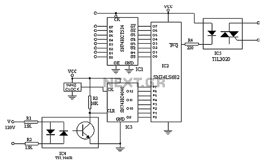
A simple digital circuit is presented that can be used to precisely control the AC power supply. This circuit does not include a digital-to-analog conversion component. In its application, effective control is established through a computer system that sends...
This circuit is designed to signal the exceeding of a fixed threshold in room noise through a flashing LED. Three fixed levels are selectable: 50, 70, and 85 dB. Two operational amplifiers provide the necessary gain for sounds captured...

This device functions as a convenient tool for testing infrared (IR) remote control transmitters used with televisions, VCRs, and similar devices. The IR signals emitted from a remote control are detected by the IR sensor module within the tester,...
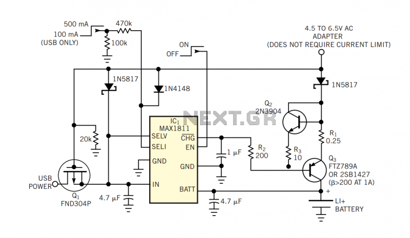
The popular USB interface can charge a portable device while transferring data. But for high-capacity batteries, the 500-mA output current of USB hosts and powered hubs greatly extends the charging time. Thus, a system that accepts charging power from...
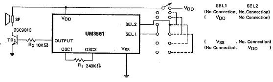
This siren alarm circuit diagram utilizes the specialized integrated circuit (IC) UM3561, which is a low-power CMOS large-scale integration (LSI) device specifically designed for such applications. The UM3561 incorporates all necessary components, including an oscillator, selector circuits, and programmed...