
Digital triac circuit diagram
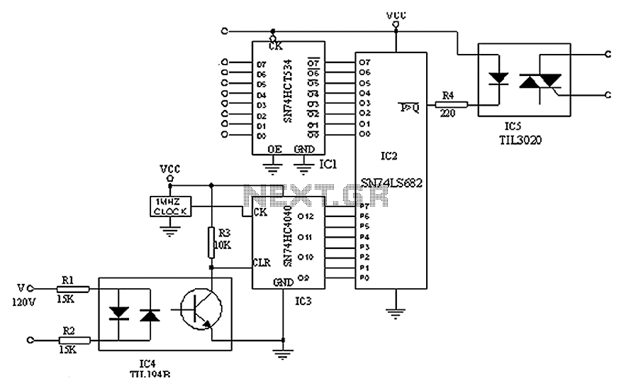
This digital circuit is designed to provide precise control over AC power supply systems, leveraging the capabilities of integrated circuits and opto-isolators for effective operation. The SN74HCT534 serves as a latch, which is critical for maintaining the state of the control signals sent from the computer system. The binary comparator SN74LS682 plays a vital role in comparing the output of the asynchronous counter SN74HC4040 with the desired reference waveform.
The SN74HC4040 operates at a frequency of 1MHz, which allows it to generate precise timing signals suitable for AC applications. This frequency is divided down to produce a stable output of 50Hz to 60Hz, aligning with standard AC mains frequencies. The zero-crossing detection is essential for ensuring that the control signals are synchronized with the AC waveform, minimizing the risk of electrical noise and ensuring smooth operation.
The use of the TIL194B optocoupler for zero-crossing detection provides electrical isolation between the high-voltage AC circuit and the low-voltage digital components, enhancing safety and reliability. The control of the triac TIL3020 through the binary output of the comparator enables the circuit to effectively switch the AC load on and off, controlled by the timing established by the asynchronous counter.
Furthermore, the possibility of integrating additional communication channels allows for scalability and flexibility in application. The inclusion of EPROM or PAL devices enables the generation of complex waveforms, expanding the circuit's functionality beyond simple on/off control to more advanced applications requiring varying power levels or specific timing sequences. This versatility makes the circuit suitable for various applications in industrial automation, lighting control, and other systems requiring precise AC power management.A simple digital circuit is shown can be used to precisely control the AC power supply, the circuit is no digital to analog conversion circuit. In the application, the effectiv e control of a computer system to send data to the SN74HCT534, after latching, by binary comparator output SN74LS682 with asynchronous counter SN74HC4040 waveform is compared. SN74HC4040 driven by a 1MHz clock, it can provide an accurate 50Hz ~ 60Hz clock. AC power zero crossing, bidirectional optocoupler TIL194B clear the output SN74HC4040 make SN74HC4040 AC signal synchronization.
In the zero-crossing point, the binary output of the comparator is invalid. Binary output of the comparator control isolation optocoupler triac TIL3020. After the zero crossing point, the counter starts counting. Binary output of the comparator remains inactive until the counter exceeds SN74HCT534 latched data. SCR optocoupler conducting half cycle of the AC signal until the next zero crossing point was closed soon. Note: You can latch, comparator and control circuit such as optocoupler more communication channels. Clock waveform counter one can drive multiple channels. Between the counter and the binary comparator waveform insert an EPROM or PAL devices, will be able to produce exponential, logarithmic or arbitrary waveform.
Related Circuits
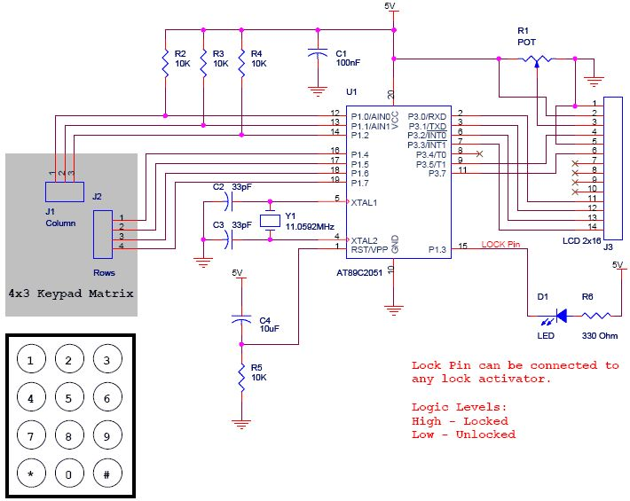
The project is a Digital Code Lock utilizing the AT89C2051 microcontroller. An LCD is employed for display purposes, and a keypad is used for inputting keys. The source code for this project is written in C. It is designed...
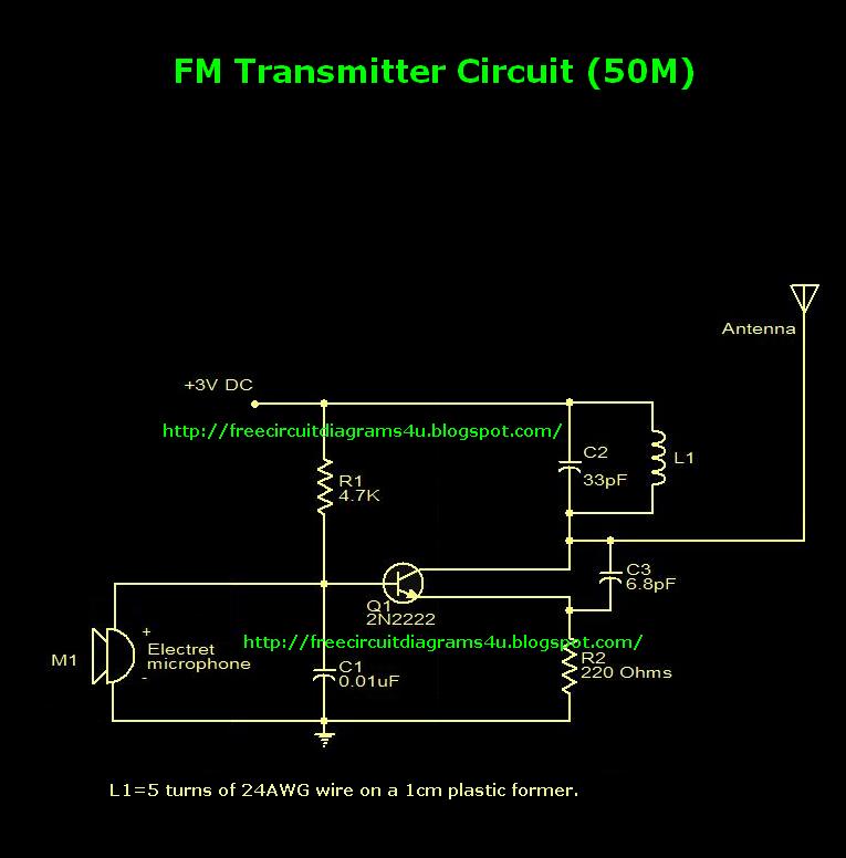
This is an FM transmitter circuit diagram. This circuit uses a 2N2222 transistor, allowing it to operate at 3V and transmit signals up to 50 meters. The FM transmitter circuit consists of several key components, primarily centered around the 2N2222...
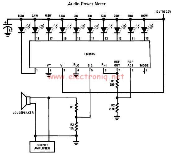
The LM3915 monolithic integrated circuit can be used to design a simple audio power level meter that senses analog voltage levels and drives ten LEDs, LCDs, or vacuum fluorescent displays, providing a logarithmic 3 dB/step analog display. One pin...
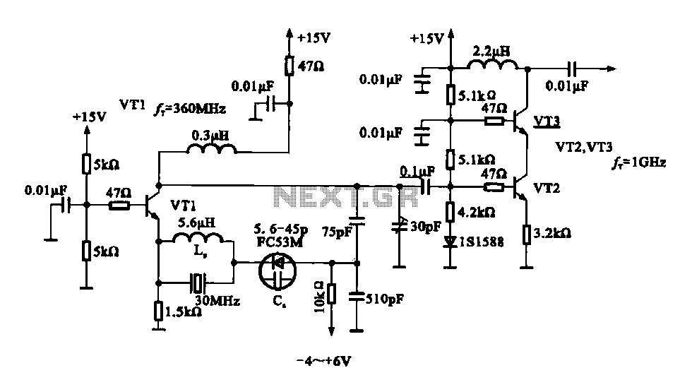
A variable frequency oscillator transistor circuit, primarily functioning as an oscillator, incorporates a crystal resonator and a varactor diode. The output is amplified, typically used for generating high-frequency signals. This 30 MHz transistor circuit features an inductor (LP) connected...
The successive approximation Analog to Digital Converter (ADC) is one of the most common types of ADC. It requires few components and is straightforward to operate. Additionally, it always takes the same amount of time to calculate the result....
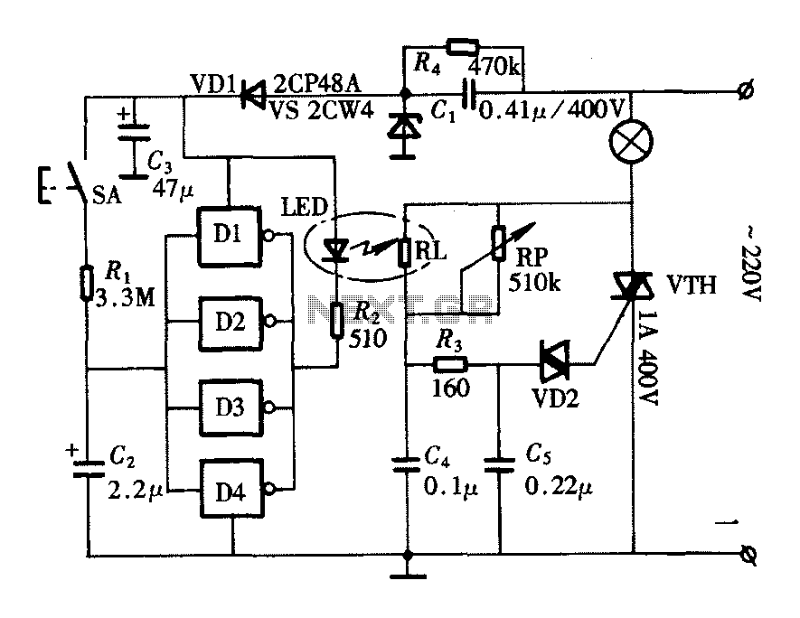
The lighting controller depicted in the figure features a gradual dimming function that prevents sudden brightness changes, which can irritate the human eye and potentially cause damage due to inrush currents. The circuit design includes a six-stage CD4069 inverter...
Warning: include(partials/cookie-banner.php): Failed to open stream: Permission denied in /var/www/html/nextgr/view-circuit.php on line 713
Warning: include(): Failed opening 'partials/cookie-banner.php' for inclusion (include_path='.:/usr/share/php') in /var/www/html/nextgr/view-circuit.php on line 713