
Accurate Low-Cost Square-Root Converter
The low-cost accurate square-root circuit typically employs operational amplifiers (op-amps), resistors, and diodes to achieve its functionality. The primary objective of this circuit is to convert an input voltage, representing a squared value, into its square root equivalent, thereby facilitating various applications in analog computing and signal processing.
The circuit design may start with a basic op-amp configuration, where the input voltage is applied to the non-inverting terminal. A feedback network composed of resistors can be utilized to establish the gain required for accurate square-rooting. Diodes may be incorporated to ensure that the output remains within the desired voltage range and to provide temperature stability, enhancing the overall accuracy of the circuit.
The output voltage, which represents the square root of the input voltage, can be further refined using additional filtering stages to minimize noise and improve signal integrity. The performance of the circuit can be evaluated by measuring the output against known square values, ensuring that the deviation from expected results remains within acceptable limits.
Applications for this square-root circuit include analog signal processing in instrumentation systems, control systems, and any scenario where a square-root function is required, such as in calculating distances in sensor applications. The low-cost nature of this circuit makes it particularly attractive for educational purposes and prototype development, allowing users to explore mathematical functions without significant financial investment.This is a Low-Cost Accurate Square-Root Circuit. This circuit is used to provide a square-root function with a good accuracy. The benefit of This circuit is. 🔗 External reference
Related Circuits
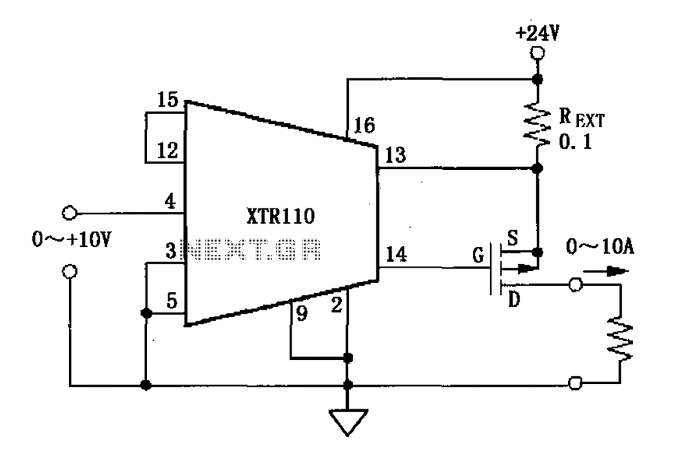
When the output current exceeds 40mA, the XTR110 requires the use of an external resistor (REXT) instead of the internal 50-ohm resistor (R9). REXT should be connected between pin 13 and pin 1. The value of REXT is determined...
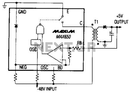
The Max650 switching regulator generates a regulated 5 V output from large negative voltages, such as the -48 V commonly found on telephone lines. This power supply requires several external components, including a transformer, and is capable of delivering...
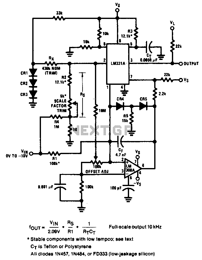
The circuit achieves an error of better than 0.02% and a nonlinearity of 0.003% within a ±20°C range around room temperature. The circuit's design focuses on precision and linearity, making it suitable for applications that require high accuracy in temperature...
The objective is to enhance information transmission by utilizing articles. Please contact us via email at [email protected] within 15 days if there are any issues related to article content, copyright, or other concerns. The articles will be removed promptly. To...
The circuit needs that the VGA card sends out the video signal in the RGB format compatible with PAL or NTSC standard video timings. This is accomplished with the right VGA to TV driver. More: This circuit is based...
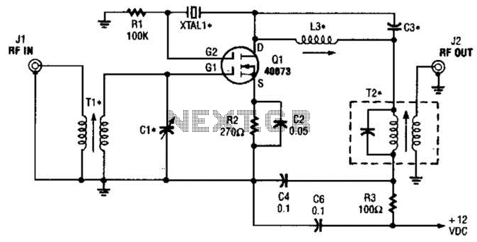
The second gate (G2) of a MOSFET can be utilized to integrate a crystal oscillator within the same stage as a frequency mixer. While this technique is common in tube technology, it is rarely implemented in dual-gate MOSFET circuits....