
Switching Regulator Converter Circuit

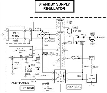
The Max650 is designed to efficiently convert high negative voltage levels into a stable 5 V output, making it suitable for applications in telecommunications and other systems that require reliable power from unconventional voltage sources. The regulator operates by utilizing a switching mechanism, which allows it to maintain high efficiency and minimize heat generation compared to linear regulators.
The inclusion of a transformer is critical in this design, as it facilitates the necessary voltage conversion and isolation. The transformer steps down the -48 V input to a level that can be further processed by the regulator circuitry. The PNP transistor serves as the main switching element, controlling the flow of current through the transformer and regulating the output voltage.
In addition to the primary components, the circuit includes various passive components such as resistors, capacitors, and inductors that help filter and stabilize the output voltage. These components work together to ensure that the output remains consistent under varying load conditions.
Furthermore, the short-circuit protection feature is essential for safeguarding both the regulator and the connected load. In the event of a short circuit, the regulator can detect the fault and automatically limit the output current, preventing damage to the system.
Overall, the Max650 switching regulator is a robust solution for generating a regulated 5 V output from high negative voltages, with built-in protection and control features that enhance its reliability and performance in demanding applications. The Max650 switching regulator produces a regulated 5 V from large negative voltages, such as the -48 V found on telephone lines. The resulting power supply operates with several external components, including a transformer, and it delivers 250 mA.
The device includes a 140-V 250-mA pnp transistor, short-circuit protection, and all necessary control circuitry.
Related Circuits
After the battery is connected, the movement of the touch stick activates the light source, which illuminates the photosensitive tube and generates a light current. This triggers the first level 3DG6 to turn on, allowing the emitter to output...
The schematic is in PDF format and cannot be sent through this site. It is recommended to check a specific website that contains various schematics, including older posts that might have the schematic needed. A WS-55807 model is experiencing...
This circuit is a wireless car alarm system composed of two modules: a transmitter and a receiver. It operates using FM radio waves and is compatible with vehicles that have a 6-12V DC power supply. If the vehicle's power...
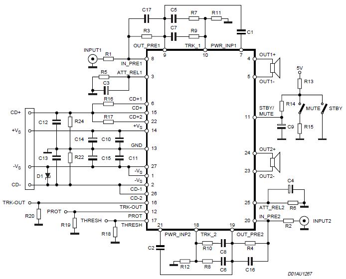
The Stereo Power Amplifier utilizes a 2x70Watt STA550 chip designed for audio power applications, featuring a BASH concept that allows connection to digital devices. This amplifier operates on a BTL (Bridge-Tied Load) system with a symmetrical power supply that...
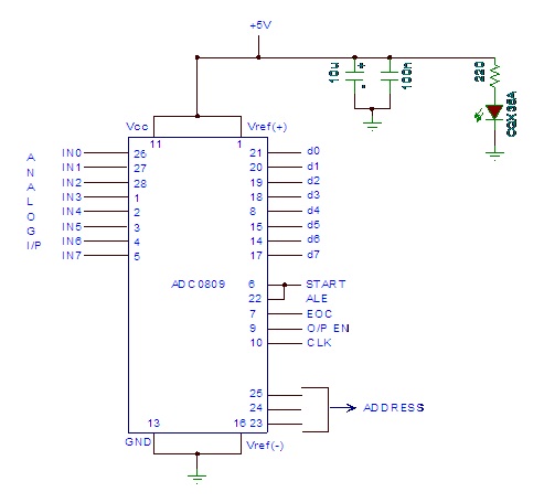
Analog to digital converter modules are utilized in microcontroller-based projects where analog signals need to be transformed into digital signals for further processing in a microcontroller. The integrated chip employed for this purpose is the ADC 0809. This post...
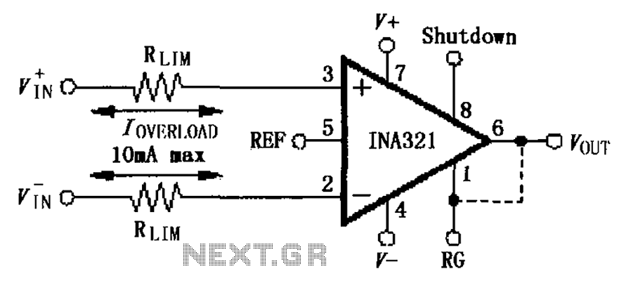
The input current protection circuit for the INA321/322 is illustrated. The INA321/322 features input terminal electrostatic discharge (ESD) protection diodes that become conductive when the input voltage exceeds the supply voltage by 500mV. The protection diodes will conduct, and...